Heat transfer – Design and rating
Choose the appropriate method, connect heat balance and geometry, and assess a heat exchanger with traceable reasoning.
No chapter found. Try another search term.
Chapter 01From process duty to suitable heat transfer
A heat exchanger combines two tasks: it must transfer a specified amount of heat while meeting the available pressure, dimensions and material constraints. A large heat-transfer coefficient alone does not answer that question. This package handbook leads from the process data sheet through calculation selection to the assessment of an actual geometry. WTS Package – Heat exchanger calculations provides the detailed follow-on guide for shell-and-tube and double-pipe equipment.
The configured package contains 130 identifiers, including complete equipment programs, individual heat-transfer methods, pressure-loss calculations, properties and supporting geometry or vibration assessments. The module map helps select a route. A row in that map does not replace detailed instructions for every construction supported by that module.
Which result do you need?
- Design: Find suitable area and geometry for a defined process duty.
- Rating: Assess achievable duty, outlet temperatures and pressure losses with a fixed geometry.
- Component calculation: Determine a heat-transfer coefficient, property or loss for an already defined flow situation.
- Change assessment: Compare a new throughput or fluid against the existing equipment.
Start with selection, the shared data sheet and the water/water example. Its increased throughput requirement leads to insufficient area. That discrepancy explains why a fully populated results window does not itself establish a suitable exchanger design.
Back to top ↑Chapter 02Choosing the right calculation route
Select by flow arrangement, phases and required result. Equipment names alone are insufficient: a tube bank in an air duct has different external flow conditions from a bundle inside a baffled shell.
| Task | Starting point | Establish first | Then assess |
|---|---|---|---|
| Shell-and-tube / double pipe | WTS | Fluids, temperatures, throughputs, permitted pressure losses | Area, actual temperatures, both pressure losses; SPIE geometry |
| Rectangular tube bank | AC | Approach flow, bundle dimensions, pitches, tube passes | Both heat-transfer coefficients, area, wall temperatures, hydraulics |
| Coil | COIL / GC | Distinguish equipment duty from flow inside an individual coil | Curvature, geometry and appropriate component calculation |
| Plate exchanger | SOWU / MM | Equipment design or individual plate channel, construction and boundaries | Heat transfer and pressure loss together |
| Single-phase internal tube flow | GB | Cross section, length, flow, fluid and wall states | Re, Pr, Nu and heat-transfer coefficient |
| Baffled shell space | WTS child route / GG | Tube bundle, baffles and active method | Shell-side geometry and loss components |
| Condensation / evaporation | KOND / VERD / suitable J or H route | Fluid purity, phase, pressure, orientation and flow pattern | Wall state, phase zones and applicability |
| Wall or environmental losses | EA / EB / TANK / WAKO | Layers, geometry, surroundings, steady state | Loss, surface temperature and insulation effect |
Names separated by a slash are alternatives with different scope; they are not an automatic calling sequence. Check the module description to establish whether you are calculating equipment or a single process. EC and GG occur in package configuration and sources but are absent from the two inspected Web registers. This table therefore cannot establish their standalone Web availability.
Back to top ↑Chapter 03Module map: all 130 package members
This overview covers all 130 saved package members by engineering task. Display and internal module names may differ. The grouping supports selection; it does not claim live availability of every identifier.
Equipment and overall duties
First establish construction, flow arrangement and duty. Component methods provide contributions applicable to that geometry.
| Identifier / display | Task | Context |
|---|---|---|
| AC | Design of tube register heat exchangers | Selection guidance; standalone detailed guide is separate. |
| ACOI | Heat transfer during flow around tube spirals | Selection guidance; standalone detailed guide is separate. |
| BEHE | Trace heating system | Selection guidance; standalone detailed guide is separate. |
| BIFL | Humid-air balance: desuperheating and condensation | Selection guidance; standalone detailed guide is separate. |
| BREN | Calculation of film temperature in thermal oil heaters | Selection guidance; standalone detailed guide is separate. |
| CA / C1 | Heat Exchangers: Calculation Methods | Selection guidance; standalone detailed guide is separate. |
| CD / C4 | Heat Transfer Networks | Selection guidance; standalone detailed guide is separate. |
| CIRC | Heat transfer and pressure drop for shell and tube heat exchanger with disk and doughnut baffles | Selection guidance; standalone detailed guide is separate. |
| COIL | Coil heat exchangers | Selection guidance; standalone detailed guide is separate. |
| DNK | Steam residual-steam condensation in heat exchanger groups | Selection guidance; standalone detailed guide is separate. |
| DSTR | Steam generator radiation loss | Selection guidance; standalone detailed guide is separate. |
| ELLU | Design of electric tube register heaters | Selection guidance; standalone detailed guide is separate. |
| KOND | Condensers for pure vapours | Selection guidance; standalone detailed guide is separate. |
| NAVE | Heat transfer in evaporators | Selection guidance; standalone detailed guide is separate. |
| OPTD | Optimisation of pressure drops in shell-and-tube heat exchangers according to VDI | Selection guidance; standalone detailed guide is separate. |
| REG / N1 | Heat transfer in regenerators | Selection guidance; standalone detailed guide is separate. |
| RIR | Heat transfer and pressure drop in doublepipe-plugin ('tube-in-tube') elements | Selection guidance; standalone detailed guide is separate. |
| RS3 | Heat transfer and pressure drop in triple tubes | Selection guidance; standalone detailed guide is separate. |
| SOWU | Plate heat exchangers | Selection guidance; standalone detailed guide is separate. |
| TANK | Calculation of heat loss of storage tanks | Selection guidance; standalone detailed guide is separate. |
| TAVA | Pressure curve during cooling of hot storage tanks with vacuum breakers | Selection guidance; standalone detailed guide is separate. |
| VERD | Vaporization of pure substances in shell-and-tube or double pipe heat exchangers | Selection guidance; standalone detailed guide is separate. |
| WAK | Flue gas heat exchanger | Selection guidance; standalone detailed guide is separate. |
| WTS | Thermal and hydraulic design of shell and tube and double pipe heat exchangers | Detailed WTS handbook |
| ZIKT / PILLOW | Heat transfer and pressure loss in pillow plates | Selection guidance; standalone detailed guide is separate. |
Geometry and vibration
Cross-check tube count, pitches, support and passes against the thermal calculation.
| Identifier / display | Task | Context |
|---|---|---|
| SPIE | Tube sheet data | Selection guidance; standalone detailed guide is separate. |
| RBSA | Tube bundle vibration analysis | Selection guidance; standalone detailed guide is separate. |
| GVLV | Tube bundle vibration analysis | Selection guidance; standalone detailed guide is separate. |
Property states
Match fluid, temperature, pressure and phase to the relevant flow space.
| Identifier / display | Task | Context |
|---|---|---|
| LUFT | Properties of air | Selection guidance; standalone detailed guide is separate. |
| N2 | Properties of nitrogen | Selection guidance; standalone detailed guide is separate. |
| NH3 | Properties of ammonia | Selection guidance; standalone detailed guide is separate. |
| O2 | Properties of oxygen | Selection guidance; standalone detailed guide is separate. |
| TOIL / T-OIL | Properties of thermal oils | Selection guidance; standalone detailed guide is separate. |
| HFO | Properties of heavy fuel oils | Selection guidance; standalone detailed guide is separate. |
Evaporation and boiling
Check orientation, flow pattern, fluid system and distance from critical boiling conditions.
| Identifier / display | Task | Context |
|---|---|---|
| HAB1 / H2 | Pool boiling of pure substances and mixtures | Selection guidance; standalone detailed guide is separate. |
| HAB2 / H2.2 | Boiling in natural convection without bubble formation | Selection guidance; standalone detailed guide is separate. |
| HAB3 / H2.3.5.1 | Pool boiling of pure substances and mixtures | Selection guidance; standalone detailed guide is separate. |
| HAB4 / H2.3.5.2 | Pool boiling of pure substances and mixtures | Selection guidance; standalone detailed guide is separate. |
| HAB5 / H2.3.5.3 | Pool boiling of pure substances and mixtures | Selection guidance; standalone detailed guide is separate. |
| HAB6 / H2.4 | Pool boiling of pure substances and mixtures | Selection guidance; standalone detailed guide is separate. |
| HAB7 / H2.5.1 | Pool boiling of pure substances and mixtures | Selection guidance; standalone detailed guide is separate. |
| HAB8 / H2.6 | Pool boiling (natural convection):Film boiling | Selection guidance; standalone detailed guide is separate. |
| HABA | Reference value of heat transfer coefficient for nucleate boiling on bare tubes and flat walls (pool boiling, flow boiling of saturated liquids) | Selection guidance; standalone detailed guide is separate. |
| HBA / H3.4 | Flow boiling of subcooled liquids | Selection guidance; standalone detailed guide is separate. |
| HBB1 / H3.2 | Flow boiling – Flow forms in evaporator tubes | Selection guidance; standalone detailed guide is separate. |
| HBB2 / H3.5.1.1 | Flow boiling of saturated, pure liquids: Convective flow boiling in vertical tubes | Selection guidance; standalone detailed guide is separate. |
| HBB3 / H3.5.1.2 | Flow boiling of saturated, pure liquids: Convective flow boiling in horizontal tubes | Selection guidance; standalone detailed guide is separate. |
| HBB4 / H3.5.2.1 | Flow boiling of saturated, pure liquids: Nucleate boiling in vertical tubes | Selection guidance; standalone detailed guide is separate. |
| HBB5 / H3.5.2.2 | Flow boiling of saturated, pure liquids: Nucleate boiling in horizontal tubes | Selection guidance; standalone detailed guide is separate. |
| HBC / H3.6 | Flow boiling - Critical boiling states | Selection guidance; standalone detailed guide is separate. |
| HBD / H3.7 | Flow boiling - Post boiling crisis heat transfer | Selection guidance; standalone detailed guide is separate. |
| LAMO | Heat transfer in forced-flow boilers | Selection guidance; standalone detailed guide is separate. |
Condensation and films
Distinguish pure fluid or mixture, film flow, superheating and subcooling.
| Identifier / display | Task | Context |
|---|---|---|
| HEAT | Condensation heat Incremental calculation | Selection guidance; standalone detailed guide is separate. |
| JA3 / J1.3 | Film condensation of pure vapours: Condensation on vertical surfaces | Selection guidance; standalone detailed guide is separate. |
| JA4 / J1.4 | Film condensation of pure vapours: Condensation at horizontal tubes | Selection guidance; standalone detailed guide is separate. |
| JA5 / J1.3 | Film condensation of pure vapours: Condensation in horizontal tubes | Selection guidance; standalone detailed guide is separate. |
| JA6A / J1.6.2 | Film condensation of pure vapours: Condensation of metal vapours | Selection guidance; standalone detailed guide is separate. |
| JA6B / J1.6.3 | Film condensation of pure vapours: Condensation of superheatet vapour | Selection guidance; standalone detailed guide is separate. |
| JBA / J2 | Condensation of multicomponent mixtures | Selection guidance; standalone detailed guide is separate. |
| JC / J3 | Dropwise condensation | Selection guidance; standalone detailed guide is separate. |
| JDB / J4 | Mix and injection condensation | Selection guidance; standalone detailed guide is separate. |
| KON1 | Condensation in horizontal tubes Incremental calculation | Selection guidance; standalone detailed guide is separate. |
| KON2 | Condensation in vertical tubes Incremental calculation | Selection guidance; standalone detailed guide is separate. |
| MD / M3 | Heat transfer to vertical falling films | Selection guidance; standalone detailed guide is separate. |
| RIES | Heat transfer in falling films at horizontal tubes | Selection guidance; standalone detailed guide is separate. |
Radiation and conduction
Establish geometry, surfaces and boundary temperatures; separate steady and transient tasks.
| Identifier / display | Task | Context |
|---|---|---|
| CB / C2 | Heat Exchangers: Heat Transfer and Heat Transfer Coefficients | Selection guidance; standalone detailed guide is separate. |
| DEE / M11 | Thermal Conductivity of Beds | Selection guidance; standalone detailed guide is separate. |
| EA / E1 | Steady conduction of heat | Selection guidance; standalone detailed guide is separate. |
| EB / E1.2 | Heat loss of walls and pipeworks | Selection guidance; standalone detailed guide is separate. |
| EC / E2 | Heat conduction - unsteady | Source/mask candidate; standalone Web registration unresolved. |
| KA / K1 | Surface heat radiation | Selection guidance; standalone detailed guide is separate. |
| KB / K2 | Heat radiation - View factors | Selection guidance; standalone detailed guide is separate. |
| KC / K3 | Heat radiation from gases and gas mixtures | Selection guidance; standalone detailed guide is separate. |
| KD / K4 | Thermal radiation from gas-solids mixtures | Selection guidance; standalone detailed guide is separate. |
| KE / K5 | Thermal radiation in furnaces | Selection guidance; standalone detailed guide is separate. |
| KF / K6 | Heat radiation - Superinsulations | Selection guidance; standalone detailed guide is separate. |
| WAKO | Heat transmission through multilayer plane walls and pipes | Selection guidance; standalone detailed guide is separate. |
Hydraulics and multiphase flow
Identify loss component, reference flow area, phase and operating point.
| Identifier / display | Task | Context |
|---|---|---|
| KV | Fittings | Selection guidance; standalone detailed guide is separate. |
| LB / L1.2 | Pressure drop in flowed through pipes | Selection guidance; standalone detailed guide is separate. |
| LBA / L2.1 | Calculation of phase fractions for gas-liquid flows | Selection guidance; standalone detailed guide is separate. |
| LBB / L2.2 | Pressure drop of gas-liquid flows in pipes, line elements and fittings | Selection guidance; standalone detailed guide is separate. |
| LBG / L2.7 | Wet pressure loss and emptying of tower trays | Selection guidance; standalone detailed guide is separate. |
| LC / L1.3 | Pressure drop in flowed through pipes with changes in cross section | Selection guidance; standalone detailed guide is separate. |
| LD / L1.4 | Pressure drop of tube bundles in cross flow | Selection guidance; standalone detailed guide is separate. |
| LDA / L4.1 | Formation and movement of droplets and bubbles in technical apparatus | Selection guidance; standalone detailed guide is separate. |
| LDB / L1.4 | Pressure drop of tube bundles in cross flow | Selection guidance; standalone detailed guide is separate. |
| LE / L1.6 | Pressure drop in flow through beds | Selection guidance; standalone detailed guide is separate. |
| LF / L3.2 | Flow patterns and pressure drop in fluidized beds | Selection guidance; standalone detailed guide is separate. |
| LG / H3.3 | Flow Boiling – Pressure drop in flow through evaporator tubes | Selection guidance; standalone detailed guide is separate. |
| LJA / L3.4 | Cyclones to separate particles | Selection guidance; standalone detailed guide is separate. |
| LJB / L4.3.3 | Droplet separation in technical apparatus: Cyclones | Selection guidance; standalone detailed guide is separate. |
| LJC / L4.3.4 | Lamellar drop separator | Selection guidance; standalone detailed guide is separate. |
| LL / L2.6 | Pressure drop and flood point in trickled beds of packing | Selection guidance; standalone detailed guide is separate. |
| LM / L1.5 | Pressure drop tube overflowed bundles in shell and tube heat exchangers with and without baffles | Selection guidance; standalone detailed guide is separate. |
| LN / N3.3 | Heat transfer and Power consumption in stirred vessels: Stirring Power | Selection guidance; standalone detailed guide is separate. |
| LOMA | Flow type diagram for two-phase flow Lockhart-Martinelli diagram | Selection guidance; standalone detailed guide is separate. |
Convection and special surfaces
Relate approach flow, cross section, boundary condition and correlation to the actual geometry.
| Identifier / display | Task | Context |
|---|---|---|
| DRLL | Heat transfer and pressure drop in corrugated tubes | Selection guidance; standalone detailed guide is separate. |
| FA / F2 | Heat transfer with natural convection | Selection guidance; standalone detailed guide is separate. |
| FB / F5 | Thermal output of heating appliances operating with hot water | Selection guidance; standalone detailed guide is separate. |
| FC / F3 | Heat transfer with natural convection: Internal flows | Selection guidance; standalone detailed guide is separate. |
| FD / F4 | Heat transfer with natural convection: special cases | Selection guidance; standalone detailed guide is separate. |
| FE / F2.5 | Combined natural and forced convection | Selection guidance; standalone detailed guide is separate. |
| G8SC / Unterkühlung | Heat transfer and pressure loss in a condenser subcooling zone | Selection guidance; standalone detailed guide is separate. |
| GA / G4 | Heat transfer with forced convection: Longitudinal flow past plane walls | Selection guidance; standalone detailed guide is separate. |
| GB / G1 | Heat transfer with forced convection: Pipe flow | Operation and field references in this book |
| GC / G3 | Heat transfer with forced convection: Flow-though coils | Selection guidance; standalone detailed guide is separate. |
| GD / G2 | Heat transfer with forced convection: Concentric annulus and rectilinear gap | Selection guidance; standalone detailed guide is separate. |
| GE / G6 | Heat transfer with forced convection: Cross-flow around individual tubes, wires, and profiled cylinders | Selection guidance; standalone detailed guide is separate. |
| GEV8 / G5 | Heat transfer with forced convection: Moving surfaces with parallel overflow | Selection guidance; standalone detailed guide is separate. |
| GF / G7 | Heat transfer with forced convection: Cross flow though single tube rows and through tube bundles | Selection guidance; standalone detailed guide is separate. |
| GG / G8 | Heat transfer with forced convection: Shell side in baffeled shell and tube heat exchangers | Source/mask candidate; standalone Web registration unresolved. |
| GGLR | Heat transfer and pressure drop in shell and tube heat exchangers with lengthwise finned tubes | Selection guidance; standalone detailed guide is separate. |
| GGO | Heat transfer and pressure drop in lengthwise flown shell and tube heat exchangers | Selection guidance; standalone detailed guide is separate. |
| GGRI | Heat transfer in external low fin tubes in shell and tube heat exchangers with segmental baffles | Selection guidance; standalone detailed guide is separate. |
| GH / G9 | Heat transfer with forced convection: Flow through beds of solids | Selection guidance; standalone detailed guide is separate. |
| GK / G10 | Heat transfer with forced convection: Impingement flow | Selection guidance; standalone detailed guide is separate. |
| INLR | Heat transfer and pressure drop in internally finned tubes | Selection guidance; standalone detailed guide is separate. |
| MA / N3.2 | Heat transfer and Power consumption in stirred vessels: Heat transfer | Selection guidance; standalone detailed guide is separate. |
| MB / M1 | Heat transfer on finned tubes | Selection guidance; standalone detailed guide is separate. |
| MC / M2 | Heat transfer through walls clad with welded tubes | Selection guidance; standalone detailed guide is separate. |
| ME / M4 | Heat transfer to non-newtonian liquids | Selection guidance; standalone detailed guide is separate. |
| MF / M5 | Heat transfer in fluidized beds | Selection guidance; standalone detailed guide is separate. |
| MG / M6 | Heat transfer from a heated surface to fixed or stirred beds | Selection guidance; standalone detailed guide is separate. |
| MK / M8 | Moistening and dehumidify of air | Selection guidance; standalone detailed guide is separate. |
| ML / N5 | Heatpipe | Selection guidance; standalone detailed guide is separate. |
| MM / N6 | Pressure drop and heat transfer in plate heat exchangers | Selection guidance; standalone detailed guide is separate. |
| MO / M10 | Heat transfer and heat flow in rarefied gas | Selection guidance; standalone detailed guide is separate. |
| SPIR | Heat transfer in pipe flow with and without twisted-tape inserts | Selection guidance; standalone detailed guide is separate. |
| TWIS | Laminar flow heat transfer in tubes with/without helical inserts | Selection guidance; standalone detailed guide is separate. |
| WROK | Heat transfer during cross flow through tube bundles with small tube pitch | Selection guidance; standalone detailed guide is separate. |
Chapter 04Preparing one shared data sheet
Record the duty once and give each side an unambiguous name. In WTS, inside/outside means tube/shell; it does not universally mean hot/cold. Another duty may place the hot fluid in the shell. Keep the mapping consistent through property selection, geometry and result assessment.
| Area | Record | Purpose |
|---|---|---|
| Process | Fluid and composition on each side; inlet and target outlet temperature; mass flow | Balance and phase state |
| Pressure | Separate absolute property-state pressure, available pressure loss and mechanical design pressures | A property pressure is neither a differential pressure nor a strength assessment |
| Geometry | Tube inside/outside diameters, wall, count per pass, active length, shell, pitch, baffles | Flow area, transfer area and loss components |
| Surfaces | Tube material, conductivity, fouling resistance on a stated area basis | Overall heat transfer and wall temperatures |
| Operation | Normal duty, part load, startup, available pump head | The strongest thermal case need not be the governing hydraulic case |
| Calculation basis | Module/construction, method/edition, language and units | Comparison requires matching boundary conditions |
Constraints and free results
Mark fixed quantities on the data sheet. In the example both target temperature pairs and shell mass flow are prescribed, while tube mass flow is calculated. If both mass flows are also fixed, the balance must agree or another quantity must be released. Do not replace an unknown with zero. After each entry, check the accepted value, unit and constraint state.
For existing equipment, actual length is a fixed boundary condition. Required length may also appear as an assessment result; it does not change the installed length automatically. Record them separately so that the next user does not inadvertently redesign the equipment.
Back to top ↑Chapter 05Engineering foundations of heat transfer
WTS learning path: this section reuses the jointly maintained WTS authoring source. Continue in the complete WTS handbook.
The tube side is not necessarily the hot side
Inside/tube side and outside/shell side identify the flow space. Either can release or absorb heat, depending on the duty. Assign process data to the actual connections and flow arrangement rather than relying on the colours in a sketch.
Energy balance and signs
For a single-phase fluid with a suitable mean heat capacity, this is the most useful preliminary check. In the WTS example shown here, cooling produces a negative duty and heating a positive duty. With no heat loss, Q̇ᵢ + Q̇ₐ ≈ 0 for that case. Compare magnitudes when assessing transferred duty, but retain signs when checking the balance. For phase changes or strongly varying properties, an enthalpy balance Q̇ = ṁ · Δh is more appropriate; the simple cp relation is insufficient on its own.
Driving temperature difference
Finite area transfers heat only with a driving temperature difference. For ideal countercurrent flow the terminal differences are ΔT₁ = Th,in − Tc,out and ΔT₂ = Th,out − Tc,in. For positive terminal differences:
If the two differences are equal, the limiting value is that common difference; the expression 0/0 is not a physical failure. Negative or vanishing temperature approaches, however, require engineering review. A temperature cross is not inherently impossible in countercurrent flow: the local driving difference matters, not simply the comparison between the two outlet temperatures.
Area, film coefficients and overall coefficient
This is an overview of the usual thermal relationship, not a complete substitute equation for every WTS special case. FN accounts for the actual flow arrangement relative to an idealized temperature profile. Additional corrections, such as those associated with longitudinal baffles, may apply.
The film coefficients αᵢ and αₐ each describe heat transfer between a fluid and the wall. The overall coefficient k combines both film resistances, tube-wall conduction and fouling. For a plain cylindrical tube, on an outside-area basis, the schematic relationship is:
All quantities must use a consistent area basis. Finned tubes and other special geometries require additional area ratios and efficiencies. Never import an external k value without knowing its reference area.
Why higher velocity is not always better
Higher velocity can improve heat transfer, but often increases pressure loss, pumping requirements, erosion or vibration loading. Reducing baffle spacing changes crossflow, window flow, end zones and the number of turns simultaneously. These effects are coupled: a seemingly optimal α value does not establish an optimal exchanger.
Understanding dimensionless quantities
The Reynolds number Re = ρ·v·d/μ compares inertial and viscous effects; the Prandtl number Pr = cₚ·μ/λ relates momentum and thermal transport. Characteristic length and validity range depend on the child module. A familiar pipe-flow threshold must not be transferred uncritically to complex shell-side flow.
Chapter 06How the component calculations work together
WTS combines the duty and calls appropriate component modules according to fluid, phase and construction. Children visible in the chapter tree belong to that WTS instance. For assessment, open that child to see the associated geometry and property state. A separately started GB or SPIE module initially represents a separate calculation.
Three forms of data transfer
- Child call: The parent passes data and takes back selected results through its implemented workflow. Not every visible child quantity is returned.
- Variable connection: The user explicitly selects a source quantity and a compatible target field. That connection carries that particular quantity, not a whole equipment definition.
- Manual transfer: Transfer value, unit, reference state and origin together. Recheck the transfer after an upstream change.
A changed tube count changes flow per tube; a different wall changes bore and resistance; another length changes area and pressure loss. Follow the whole chain after a geometry revision. The example demonstrates returning from insufficient area to a geometry decision. The solver's execution order is not a rigid diagram traversed just once.
Back to top ↑Chapter 07The operating principle: constraints, results and solver
WTS learning path: this section reuses the jointly maintained WTS authoring source. Continue in the complete WTS handbook.
SOL ALPHA does not impose a rigid distinction between permanently designated input and output fields. Its internal equation solver uses known quantities to determine unknowns supported by the selected module path. The same physical quantity can therefore be an input constraint in one task and a calculated result in another.
This flexibility does not mean every mathematical rearrangement is available in every module. Selection fields, discrete tube counts, tables, validity limits and iterative solution paths impose restrictions. Several geometries may satisfy the same thermal duty. An inverse calculation consequently needs an unambiguous question.
Four questions for each important field
- Is the value known? An empty or unknown result is not zero.
- Is it a constraint or a result? A calculated value may change after another input.
- Is it fixed? A fixed constraint should not be replaced by another equation.
- Is it connected? Another module instance or child chapter may be its authoritative source.
Entering values safely
Click the correct numerical field, enter the value and confirm it, for example using Tab. Wait for processing to finish before changing more dependent fields. Afterwards, check the value actually accepted and its displayed unit.
The general SOL ALPHA input system also supports expressions and units. 100 + 200 is arithmetic, not a list. 1 bar is a physical input that can be converted into the field's compatible unit. For WTS, pay particular attention to whether a pressure field requires absolute pressure. Unit conversion does not by itself convert gauge pressure into absolute pressure.
Reading field colours
In the standard mask, calculated numbers commonly use a teal colour or corresponding field style, while ordinary constraints look different. Connected variables and highlighted dependencies can receive additional colours or markings. Colour is a navigation aid, not sufficient evidence on its own: inspect Variable info, fixed status and connection source when uncertain. Themes, focus and active highlights can alter appearance.
Releasing a variable
To prescribe a previously calculated result, a suitable other constraint must become free. Open the field's context menu and use the available release or inverse-calculation action. Check which quantity the solver determines afterwards. Do not release several boundary conditions indiscriminately: this may leave the problem underdetermined or move it towards a different geometry.
In WTS the consequences often span several chapters. Changing tube count may affect SPIE, velocities, heat-transfer coefficients and pressure losses. Changing fluid or temperature propagates through fluid properties to required area. Wait for the complete calculation to finish and inspect its messages.
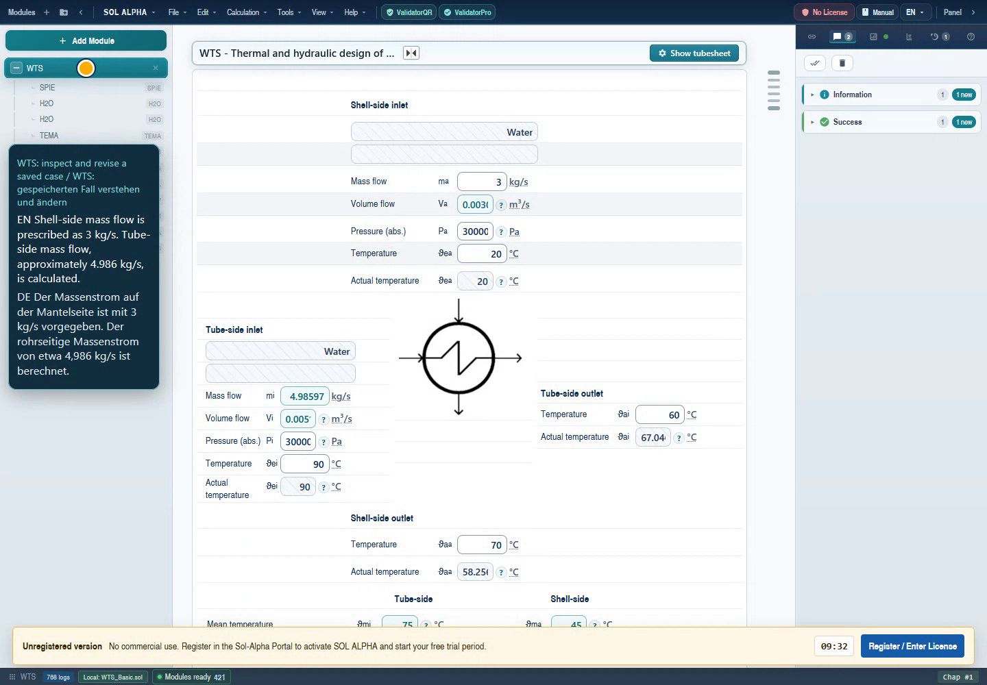
- Shell mass flow: the prescribed 3 kg/s in this case.
- Tube mass flow: a calculated result in this case.
- WTS and its children in the project tree.
Unaltered frame from the 6 September 2026 demo; English UI with the original bilingual video captions. Full-size original
Chapter 08First start: from module browser to calculation mask
WTS learning path: this section reuses the jointly maintained WTS authoring source. Continue in the complete WTS handbook.
- Open a separate demonstration or practice project. Do not use an unsaved production design as an exercise workspace.
- Search the module browser for WTS. Select the heat-exchanger module and read its description. A special version offered alongside it is not automatically the standard configuration.
- Open the module. Where the launch path requires it, the basic-data selection dialog appears. A loaded project may instead show its saved mask immediately.
- Select both fluids and phases in basic-data selection. Then check tube and shell geometry, bundle type, installation orientation, baffles and any special tubes.
- Review the summary and confirm the configuration using the offered action. A check mark in the dialog navigation indicates completeness of dialog entries, not engineering suitability.
- Complete operating data in the calculation mask from top to bottom. After each useful input group, check accepted values, units and messages.
- Inspect WTS child chapters in the module tree to understand the origin and state of important intermediate results. Return to the parent WTS afterwards.
- Review evaluation and results. Save a clearly named practice variant only once you understand which values are fixed constraints and which have been calculated.
Finding your way around
Project modules and indented child chapters appear on the left, the active calculation mask in the centre, and information and warnings on the right. Their exact position depends on the layout. WTS has several thematic mask sections; deliberately scroll to evaluation and results instead of treating the upper operating-data area as the whole calculation.
The basic-data button or module-specific special menu returns to configuration. Confirming again is not a view-only operation: selections and defaults may be applied. Save a variant before a major reconfiguration and compare the governing constraints afterwards.
When a dialog is waiting
An open selection, tube-layout or fluid-property dialog is part of the active calculation workflow. Close it deliberately with Apply or Cancel. Repeated background recalculation does not replace the pending decision. If a dialog remains open despite an appropriate selection, capture the message and last action instead of opening several more WTS instances.
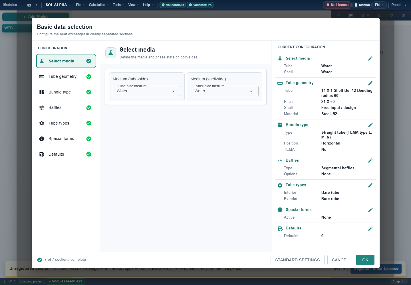
- The seven areas guide configuration.
- Select tube and shell fluids separately.
- Review the summary before applying.
- OK applies settings; checkmarks do not approve the engineering design.
Existing program screenshot; capture time not independently documented. Full-size original
Chapter 09Selecting fluids, phases and properties
WTS learning path: this section reuses the jointly maintained WTS authoring source. Continue in the complete WTS handbook.
Fluid selection is part of the calculation, not merely a label. It determines which property module WTS creates and which temperatures, pressures and compositions it uses to evaluate properties. Open the basic-data dialog and configure tube and shell sides separately. Then check the transferred settings in the main mask.
Procedure for each side
- Assign the actual fluid to the tube or shell side. The hot fluid does not have to be inside the tubes.
- Select the fluid and an available phase. Liquid, gas and condensation do not use the same model.
- Supply the requested additional information: glycol product and concentration, frost protection, salinity, oil grade, acid concentration or gas composition.
- Apply the selection. Enter operating pressure and temperatures in the main mask, using the correct pressure reference.
- Open the corresponding property chapter and inspect density, heat capacity, thermal conductivity and viscosity. Phase change also requires saturation state, enthalpy, vapour quality and latent heat.
Water, steam, gases and mixtures
H2O provides water/steam states; a liquid-water calculation and steam condensation are nevertheless different duties. Air, nitrogen, oxygen, helium, CO₂ and ammonia have their own routes. Natural gas distinguishes predefined L/H cases from free composition input. Humid gas uses HX; condensate and latent heat cannot be treated as though the gas were dry.
Glycol does not automatically mean an arbitrary water/glycol mixture. Choose the offered product and supply its concentration or frost-protection parameter as requested. Oils require a product type and, where applicable, ISO grade and density. For acids, sodium hydroxide, sucrose, seawater and beer/wort, composition is part of the duty. A fluid name alone is insufficient.
Free property input and external property sources
Free input / SDAT is useful when reliable properties are available outside the built-in selection. Record their source, temperature and pressure range, composition and units. A single room-temperature value is not an adequate basis for a wide temperature change or strongly temperature-dependent viscosity. PROP/Proper and STAB are separate property routes; the available selections depend on installation and datasets.
The fluid reference maps all 32 historical fluid identifiers to property modules. Historical glycol identifier 10 is not a replacement for current selection 15.
Back to top ↑Chapter 10Defining tubes, shell and passes
WTS learning path: this section reuses the jointly maintained WTS authoring source. Continue in the complete WTS handbook.
The basic-data dialog groups fluids, geometry, bundle, baffles, tube forms, special forms and defaults. Visible and editable fields depend on the selection. Start with a simple geometry corresponding to the real equipment, then add any special features.
Tubes and shell
Distinguish tube outside diameter V24, inside diameter V25 and wall thickness V305. For an ordinary round tube the geometric relationship is di = da − 2s. V19 is a heat-transfer wall-thickness quantity and cannot automatically replace every construction wall dimension. Shell outside diameter V41, shell wall thickness V42 and shell inside diameter V54 form a separate dimensional chain. Select material and conductivity appropriate to operating temperature.
Use the offered tube and shell selections where appropriate. Library values simplify recurring dimensions but must still agree with drawings and supplied equipment. Save or delete personal table entries deliberately; a teaching example does not require changes to shared master data.
Pitch and passes
Transverse and longitudinal pitches V43/V44 and pitch angle V93 define the tube arrangement. Tube-side passes V55 distribute the tube cross-section across successive flow paths. Shell-side passes V97 describe a different arrangement. Doubling the number of passes therefore neither doubles the duty in general nor automatically doubles effective area. It changes velocity, heat transfer, pressure loss and temperature arrangement.
Three lengths that must not be confused
- Required bundle length V46
- The calculated length for the current thermal duty and selected geometry.
- Actual active tube length V60
- The length available for effective heat transfer. Together with tube count and reference diameter, it determines available area.
- Total tube length V196
- A construction dimension including other length contributions. Do not use it as active length without checking its definition.
Fixed dimensions or design targets?
For existing equipment, its fixed dimensions must remain intact. In a new design, desired velocities V61/V62, minimum clearances or length/diameter limits can serve as design settings. These target values are not the calculated operating velocities V53/V94. After any layout change, recheck tube count, areas and both pressure losses.
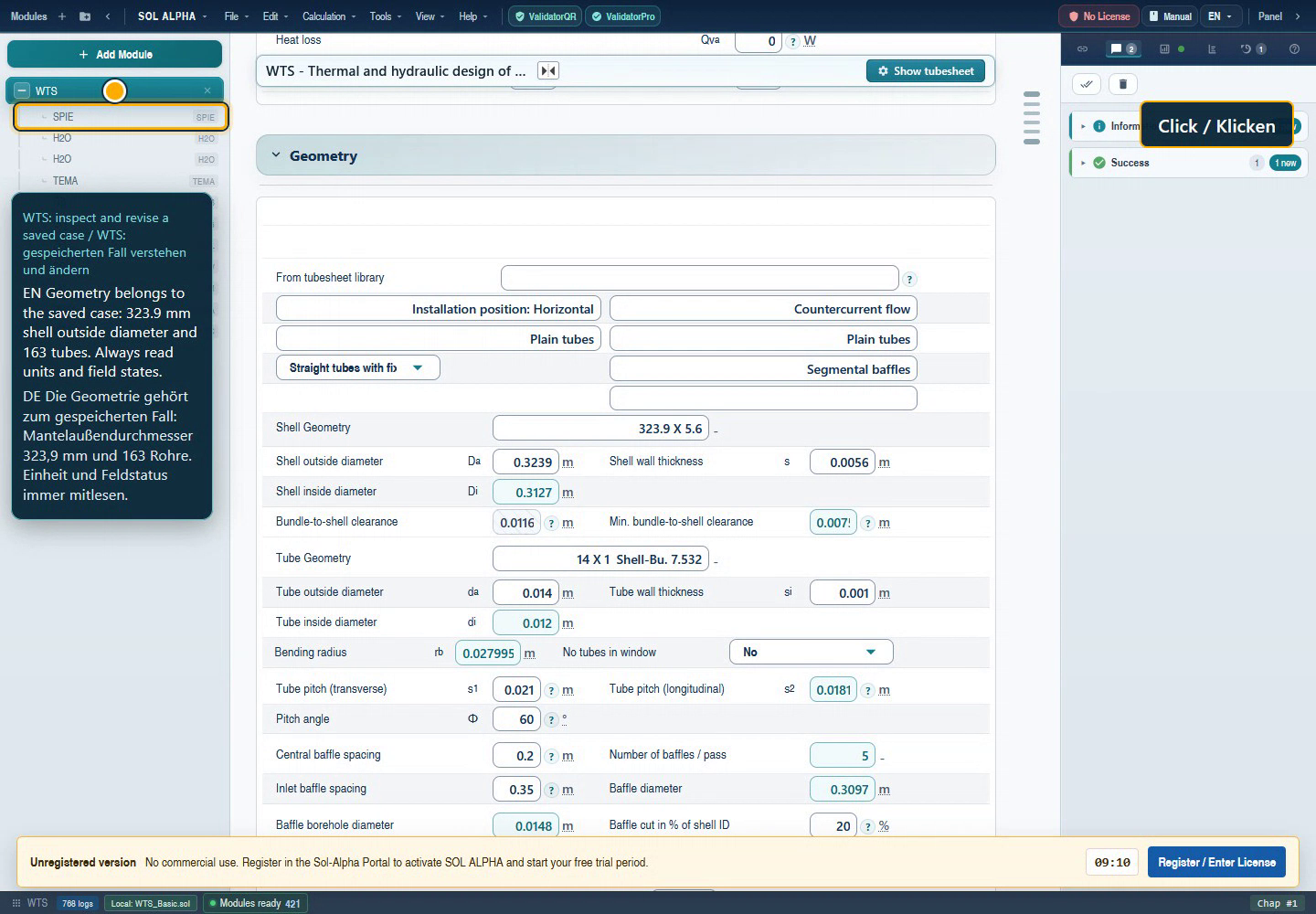
- Shell dimensions: outside, wall and inside form one chain.
- Tube dimensions: 14 × 1 mm gives 12 mm inside.
- Regular spacing and first spacing are separate fields.
Unaltered frame from the 6 September 2026 demo; English UI with the original bilingual video captions. Full-size original
Chapter 11SPIE: understanding, checking and freezing a tube layout
WTS learning path: this section reuses the jointly maintained WTS authoring source. Continue in the complete WTS handbook.
SPIE represents the tube layout: tube positions and count, pass lanes, pass arrangement, window regions and construction boundaries. This is more than a drawing. Tube count and open flow areas affect heat transfer, surface area and pressure loss. A different layout can therefore change results even when temperatures and mass flows remain unchanged.
Viewing is not redesigning
- Select the correct WTS chapter, particularly in a project containing several exchangers.
- Use “Show tubesheet” when a layout is available, or open the SPIE child belonging to that WTS.
- Check total tube count, passes, lanes, edge clearances and windows. Compare them with V47 and the parent WTS geometry.
- Close the view without changes when inspecting only. Redesigning or choosing a different library entry is an intentional geometry change.
When should a layout be frozen?
Freeze a layout when rating existing equipment or when an approved tube arrangement must remain unchanged. “Freeze/edit tube layout” changes the layout state and associated SPIE fixed state; the editing route can open the editor. “Frozen” does not mean all thermal variables are fixed. Mass flow, properties and duty can still be recalculated.
In the reviewed source, unfreezing deliberately releases selected geometry settings and clears library associations. Save a copy first. Default rules may select a different shell/tube arrangement after unfreezing. Check the returned values as well as the drawing.
Libraries and reuse
A saved layout is useful for recurring construction sizes. Before applying it, compare tube diameter, pitch, lanes, passes, shell and internals. A familiar name is insufficient. Viewing a project layout is not the same operation as saving or deleting a library entry.
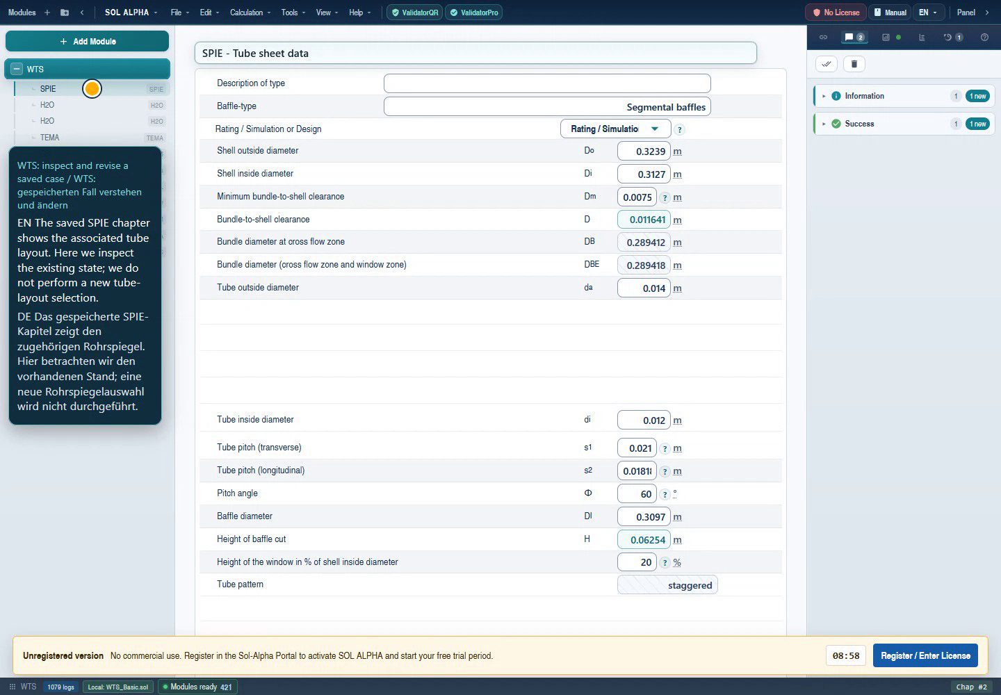
- The associated SPIE chapter is selected.
- Check rating/design mode and shell dimensions.
- Compare inside diameter and pitch with WTS.
Unaltered frame from the 6 September 2026 demo; English UI with the original bilingual video captions. Full-size original
Chapter 12Understanding GB: internal tube flow and heat transfer
GB is the appropriate component calculation for forced-convection heat transfer inside a tube or supported non-circular channel. It replaces neither the complete exchanger nor every pressure-loss calculation. When examining a WTS child, first compare length, bore, total mass flow, number of tubes flowing in parallel and the properties used.
| Step | Fields | Check |
|---|---|---|
| Define cross section | V40, V2 or V33/V34 | Circular tube: inside diameter; another section: area and wetted perimeter |
| Resolve flow | V10, V11, V12, V9 | Do not confuse total and per-tube flow; account for passes |
| Compare property state | V4, V5, V8, V35, V57 | Dynamic viscosity, density, conductivity and heat capacity refer to the selected state |
| Read wall condition | V7, V13, V39, V61 | Wall correction and thermal boundary condition match the construction |
| Interpret results | V16, V6, V19, V20 | Reynolds, Prandtl, corrected Nusselt number and heat-transfer coefficient |
| Document method | V62 | Record the edition option alongside the result |
The basic relationships in consistent SI units are Re = ρ w dₕ / μ, Pr = μ cₚ / λ and α = Nu λ / dₕ. For a non-circular section, dₕ = 4 A / U. These expressions explain the direction of a change; the actual Nusselt correlation and applicability depend on the boundary condition and method.
For an independent order-of-magnitude check, choose ρ = 1,000 kg/m³, μ = 0.001 Pa·s, w = 1 m/s and dₕ = 0.01 m: Re = 10,000. These freely chosen teaching values are neither a newly executed GB run nor a property set at a specified temperature. The check mainly detects unit or diameter errors.
Chapter 13Worked example: revising a water/water duty
WTS learning path: this section reuses the jointly maintained WTS authoring source. Continue in the complete WTS handbook.
This example uses only the existing demonstration file WTS_Basic.atl, not a customer design. It demonstrates loading, understanding and revising an existing WTS project. It is explicitly neither a fully accepted fresh design nor approved equipment.
1. Load the project and read the duty
- Save the demo locally and open it through the application's file-open function in a separate project. Saving an older ATL file can convert it to the current project format.
- Select WTS in the chapter tree. Wait until the mask has loaded and calculation has completed.
- Check water on both sides, tube-side target temperatures 90 → 60 °C and shell-side targets 20 → 70 °C.
- Read the prescribed shell mass flow of 3 kg/s. Tube mass flow is calculated in this duty, approximately 4.985974 kg/s.
The recording also shows actual-temperature fields. They differ from the prescribed outlets. Do not copy them over the target duty. The displayed pressures belong to the old demonstration data; inspect the complete pressure value and reference in the opened file, not in a narrow clipped screenshot field.
2. Cross-check geometry
The recording shows shell outside diameter 323.9 mm, shell wall 5.6 mm, 14 × 1 mm tubes and 163 tubes. A transverse pitch of 21 mm and angle of 60° belong to the saved arrangement. Actual active length is 1.5 m. Open the associated SPIE child and compare the values without selecting a new layout.
3. Change exactly one requirement
- Return to WTS.
- Change only shell mass flow V2 from 3 to 3.3 kg/s. In English input,
3.3is unambiguous; check language and unit. - Confirm and wait for recalculation to finish. Do not leave required interactions unanswered.
- Check that V2 remains prescribed and V1 remains calculated.
4. Understand the result
| Quantity | Historical demo value after revision | Meaning |
|---|---|---|
| V2 | 3.3 kg/s | New shell-side requirement |
| V1 | 5.4845715 kg/s | Calculated tube-side mass flow |
| V13 / V14 | −689.41856 / +689.41856 kW | Heat released / received |
| V21 | 19.146616 m² | Required area |
| V46 | 2.6707008 m | Required active length |
The opposite signs express the balance without heat loss. The demonstration check also compared tube duty against mass flow, cₚ and temperature change. A higher shell throughput with unchanged target temperatures demands more duty and a higher tube-side mass flow.
5. Do not stop at a coloured result
The screenshot shows only about 10.753 m² available. Against 19.147 m² required, this is clearly insufficient: approximately −43.8% area margin. Actual length 1.5 m is also below the required 2.671 m. The calculation therefore illustrates that target temperatures are not automatically achieved by the existing size. A real design would require changed geometry or duty, followed by renewed hydraulic and other checks.
6. Finish safely
Save a new copy, for example WTS-training-flow-3p3.sol. Reopen it and compare requirements, tube count, dimensions, edition, area and margin. The old video text notes a reload limitation present at that time; later fixes address geometry transfer. Neither that historical warning nor the newer fix report replaces checking the version actually in use.
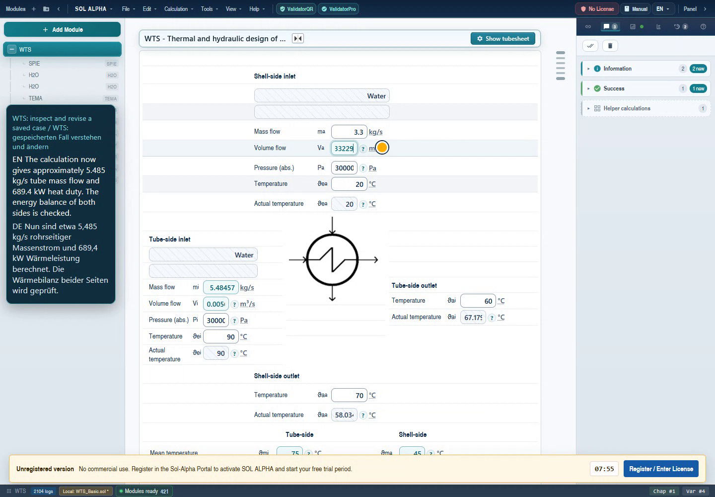
- V2 was the only input changed, to 3.3 kg/s.
- V1 follows from the duty at approximately 5.48457 kg/s.
- The actual outlet temperature still requires separate assessment.
Unaltered frame from the 6 September 2026 demo; English UI with the original bilingual video captions. Full-size original
Chapter 14FN, ZELL and actual outlet temperatures
WTS learning path: this section reuses the jointly maintained WTS authoring source. Continue in the complete WTS handbook.
A specified outlet temperature initially describes the required process duty. It does not prove that a specified small area can achieve it. In applicable configurations WTS therefore distinguishes target temperatures from calculated actual temperatures.
FN and ZELL
Temperature correction depends on tube/shell passes, arrangement, internals and exchangers in series. WTS selects FN or ZELL in the corresponding route. They are not two arbitrary safety factors to apply in parallel. A route change can remove the child that no longer applies. In certain condensation cases FN is set to 1 and the corresponding actual-temperature calculation is specifically not handled like a single-phase case.
FN factor V80 corrects the idealised temperature arrangement. V324 denotes a corrected logarithmic mean temperature difference. A low factor can indicate an unfavourable pass combination or a difficult temperature duty. Do not manually set it to 1 to remove a warning. An internal lower bound used in a calculation step is not an engineering acceptance criterion either.
Rating existing equipment
- Keep the tube layout and constructed active length fixed.
- Enter inlet temperatures and available mass flows as operating conditions.
- Check which target quantities remain fixed and which actual temperatures the selected route calculates.
- Compare actual outlet values V223/V224 with required values V10/V12 where these fields are offered and known.
- Assess heat balance, area, pressure loss and applicability messages together.
A missing actual-temperature field may reflect a construction limitation or an incomplete state. Manually copying a target value is not a substitute for a calculated actual temperature.
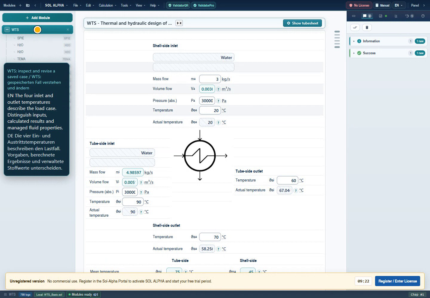
- Tube outlet: target 60 °C; actual approximately 67 °C in the recorded case.
- Shell outlet: target 70 °C; actual approximately 58 °C here.
Unaltered frame from the 6 September 2026 demo; English UI with the original bilingual video captions. Full-size original
Chapter 15Assessing results: area margin and calculation edition
WTS learning path: this section reuses the jointly maintained WTS authoring source. Continue in the complete WTS handbook.
The key result groups
- Heat balance
- V13/V14 together with V15 must match the duty. Read signs and units.
- Film and overall heat transfer
- V16/V17 describe each side; V23 combines the resistances. A high coefficient on one side can still be limited by the other side, the wall or fouling.
- Requirement and availability
- V21 and V46 are required quantities; V96 and V60 describe available area and active length. Their comparison is more useful than an isolated positive area value.
- Hydraulics and temperature achievement
- V64/V65, velocities and actual temperatures must also be acceptable.
Reading area margin correctly
For the ordinary area comparison, margin expresses available area in excess of required area:
110 m² available against 100 m² required gives +10%; 90 m² available gives −10%. Special routes can use a different area basis; the heated OhmEx route, for example, assigns heated area. Check the actual variable definition.
A margin change from 0.5% to 0.6% is 0.1 percentage points, but 20% relative to the small starting value. Automated comparison can flag this despite a small absolute margin change. Conversely, several percentage points can matter in a tight design. Record absolute and relative differences and do not apply one blanket tolerance to all quantities.
Selecting edition 11 or 12
The results section contains “Calculation according to 11th edition VDI Heat Atlas”. This is WTS variable V356: selected/1 means edition 11; cleared/0 means the newer edition-12 calculation in the inspected route. When the flag is unknown, the reviewed WTS source defaults it to 0. WTS passes this choice to GB. It is therefore not a display preference or a global switch for every equation in every module.
- Record the existing setting and save a comparison case.
- Change the visible edition option in WTS results.
- Wait for recalculation.
- Compare V16, V23, V21, V46 and V205 with otherwise identical requirements and layout.
- Record the edition in the result report.
An old archive value based on a different calculation approach is not a universal target for the new edition. Legitimate correlation changes must be distinguished from errors in geometry transfer, fluid state, fixed constraints or recalculation.
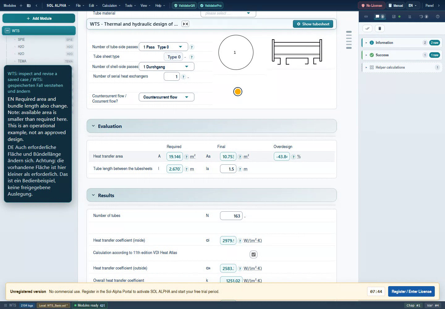
- Read required area, available area and negative margin together.
- Required length approximately 2.67 m; actual only 1.5 m.
- The edition-11 option is selected here. It affects the calculation route.
Unaltered frame from the 6 September 2026 demo; English UI with the original bilingual video captions. Full-size original
Chapter 16Inverse calculation: deliberately releasing a constraint
WTS learning path: this section reuses the jointly maintained WTS authoring source. Continue in the complete WTS handbook.
Inverse calculation makes a previously calculated quantity a target and permits a suitable former input to become unknown. It can express a new geometry or process question. It does not guarantee a unique solution for every arbitrary combination.
Example: changing tube inside diameter
A smooth tube with 14 mm outside diameter and 1 mm wall has 12 mm inside diameter. If 11 mm inside is required, decide what remains fixed: keeping 14 mm outside requires 1.5 mm wall geometrically; keeping 1 mm wall requires 13 mm outside. Holding both original constraints while additionally requiring 11 mm inside is inconsistent.
- Save a copy and record tube selection, fixed state and connection of the affected field.
- If a standard-tube selection owns the geometry, change that selection preferentially. An explicit tube selection is more meaningful than forcing a contradiction into its derived fields.
- If free geometry input is supported, open the context menu of the quantity allowed to vary and use the offered release function.
- Enter the new target with a unit and confirm.
- Check the released result and the tube layout, count, area, velocity and pressure loss. A new outside diameter may not fit the old layout.
Example: a duty target instead of fixed throughput
When both temperature changes and one mass flow are specified, duty follows from the balance. To prescribe duty instead, a suitable quantity such as a mass flow must become free. Availability and convergence of this route depend on the actual equations and fluid configuration. Do not prescribe target duty, all temperatures and all mass flows as independent requirements simultaneously.
Back to top ↑Chapter 17Finding a better geometry
The revised example has insufficient available area. Treat that as a new design question: must the requested duty remain unchanged, or is a lower throughput or different outlet temperature acceptable? Avoid changing several quantities together before understanding their individual effects.
| Change | Potential benefit | Also check |
|---|---|---|
| Increase active length | More transfer area | Pressure loss, installation length, cleaning, vibration |
| Increase tube count | More area and different flow per tube | Velocity may fall; heat transfer changes; recheck SPIE |
| Change passes | Different velocity and temperature arrangement | Pressure loss, tubes per pass, turning losses |
| Change baffle spacing | Deliberately influence shell flow | Free areas, pressure loss, vibration, applicability |
| Include fouling | More realistic operating assessment | Resistance area basis and unit; clean and fouled conditions |
| Change process requirement | Continue using existing equipment | Acceptability of revised outlet temperatures or duty in the process |
Keep a comparison table
Save the starting copy and a clearly named revision for each variant. Record the changed constraint, area, required/actual length, both velocities, both pressure losses and relevant temperature results. After each variant, confirm that material, phase, edition and constraint states still provide a consistent comparison basis.
With fixed tube count and diameter, transfer area increases in proportion to active length. This does not promise a proportional increase in achievable total duty: temperature driving force, properties and coefficients can also change. An approximately quadratic pressure-loss trend likewise requires appropriate flow and property assumptions.
Back to top ↑Chapter 18Treating phase change deliberately
The water/water demonstration is a single-phase teaching case. Condensation or evaporation requires more than selecting another fluid name. Establish where the phase change occurs, the pressure there, whether the fluid is pure or a mixture, and the orientation assumed by the selected method.
Condensation
Distinguish desuperheating, condensation itself and possible subcooling. A mean temperature must not silently merge these zones. The package includes JA routes for film condensation, JBA for multicomponent mixtures, and KOND, KON1 and KON2 for different equipment or incremental tasks. Select using the specific module description. The presence of vapour alone does not justify applying a pure-fluid method to a mixture containing non-condensable gases.
Evaporation
Separate pool boiling, flow boiling and critical boiling conditions. HAB modules address different boiling cases; HBB routes distinguish factors such as orientation and mechanism inside a tube. A high calculated heat-transfer coefficient does not establish adequate distance from a boiling crisis. Local vapour quality, heat flux and flow pattern may govern the assessment.
Practical procedure
- Record the expected phase progression on the data sheet.
- Select the method by fluid system, geometry and orientation.
- Check pressure reference and saturation state; do not transfer properties from the wrong phase.
- Read local or zone-specific results in addition to total duty.
- Assess pressure loss and the associated possible change in saturation temperature along the equipment.
This chapter supports selection. A separately executed two-phase example with evidenced values belongs to the relevant module guide; the single-phase demonstration does not establish it.
Back to top ↑Chapter 19Connecting properties, hydraulics and mechanical assessment
The thermal calculation uses data from several disciplines. Preserve engineering meaning when transferring them. Water properties may come from H2O, which belongs to the fluid-properties package; this does not justify moving that module into another product group.
Properties
Transfer fluid, composition, temperature, absolute pressure and phase with each value. Dynamic viscosity μ differs from kinematic viscosity ν = μ/ρ. Heat capacity and enthalpy serve different purposes: constant cₚ may explain a single-phase estimate, but cannot replace an appropriate enthalpy balance across phase change.
Pressure loss and plant operation
Exchanger pressure loss is only one part of the system. Piping, valves, elevation differences and connection losses need assessment on the same operating-point basis. Do not confuse a local module loss with available pump head. For gases, check whether changing density along the flow path invalidates a simplified treatment.
Mechanical assessment
Tube and shell dimensions from a thermal geometry check are not yet sufficient wall thicknesses. Transfer materials, design and test load cases, temperatures, corrosion assumptions, dimensions and possible differential pressures for mechanical assessment. AD 2000 – Pressure vessel calculations explains the starting point for connected pressure-part checks. Selection of the applicable code remains part of the project definition.
For every interface, document whether data are transferred manually or through an actual configured variable connection. Automatically equating a tube-side process temperature with a mechanical design temperature may overlook a more severe load combination.
Back to top ↑Chapter 2020 common situations and what to check
WTS learning path: this section reuses the jointly maintained WTS authoring source. Continue in the complete WTS handbook.
1. After an input, results are missing.
You have started a case or changed a requirement. Check incomplete basic data, fluid states, required dialogs and contradictory fixed values. A blank value is unknown, not zero. Start with messages and the first missing intermediate result.
Read the relevant chapter →2. Why are there two water chapters?
Both sides can contain water at different states. Identify the parent and fluid side of each property child before comparing temperatures or properties.
Read the relevant chapter →3. An input immediately changes back.
The quantity may be managed by a connection, standard selection or parent module. Inspect its origin. Change the owning source or explicit input mode instead of repeatedly editing the dependent field.
Read the relevant chapter →4. What does a teal number mean?
The standard display distinguishes calculated values by colour. Also inspect state, unit and any connection. Colour is not engineering approval and can vary with theme or state.
Read the relevant chapter →5. Area is positive, but margin is negative.
A positive required area is normal. Negative margin in the ordinary area comparison means less is available than required. Compare V21 with V96 and V46 with V60.
Read the relevant chapter →6. Target and actual temperatures differ.
You may be comparing a process requirement with the capacity of specified geometry. Insufficient area cannot achieve the target. Check the available FN/ZELL route and balance.
Read the relevant chapter →7. Why do values change when the edition changes?
WTS option V356 is passed to the internal heat-transfer route. A changed coefficient changes k, requirement and margin. Compare with identical layout and inputs.
Read the relevant chapter →8. Can I fix both mass flows and all temperatures?
Only if the requirements are mutually consistent and the selected route allows it. Otherwise the balance is over-constrained. Decide which quantity should be a result.
Read the relevant chapter →9. Tube count changes after editing a tube dimension.
A new outside diameter or pitch can require a different layout. Check whether redesign was intended or an existing geometry should have remained frozen.
Read the relevant chapter →10. The first baffle distance does not stay as expected.
Distinguish V59 from V58 and inspect the special option, fixed state and geometry source. Preserve a reproducible before/after case if a confirmed requirement is overwritten despite the appropriate mode.
Read the relevant chapter →11. Why is a special command disabled?
The function may not apply to the construction or may be owned by a parent KOND/UVERD workflow. Check the owning parent and entitlement. Internal flags are not a substitute for the UI.
Read the relevant chapter →12. Must I create every child manually?
No. The normal WTS workflow requests the appropriate children itself. Manually added modules with the same name are not automatically the children managed by WTS.
Read the relevant chapter →13. May I enter alpha from a supplier document?
The explicit manual-input mode supports this. Check side, area basis, unit and operating state, and document the value as an external assumption.
Read the relevant chapter →14. Cold-start pressure loss is much higher.
Oils in particular can be much more viscous when cold. Check cold-start temperature and properties; do not compare blindly with warm steady operation.
Read the relevant chapter →15. Is vapour quality the same as relative humidity?
No. They are different state quantities. Read the field definition and select the appropriate pure-condensation or humid-gas route.
Read the relevant chapter →16. Why does a different heat-transfer child appear?
Tube form, phase, orientation or baffle construction may have changed. GG, GGO, GD and JA modules are not merely alternative names. Check the selected physical duty.
Read the relevant chapter →17. An archive differs strongly only in relative margin.
Relative differences are unstable for margin near zero. Compare percentage points and available/required area. Conversely, large percentage-point differences must not be dismissed as rounding.
Read the relevant chapter →18. The layout looks different after reopening.
Preserve the original and reopened state. Compare count, dimensions, lanes and library/frozen state before judging the drawing. Record format, version and exact save action.
Read the relevant chapter →19. A study contains individual blank points.
Individual states may be invalid, incomplete or cancelled. Inspect each affected case. Do not fill blank results with the previous valid result.
Read the relevant chapter →20. Is the design finished when margin is positive?
No. Check pressure losses, achieved temperatures, property/model limits, vibration and the separate mechanical design. Project-specific approval follows those checks.
Read the relevant chapter →Chapter 21Saving and communicating traceable results
A useful report answers the original question first. Start with equipment and operating case, requested duty, geometry actually assessed and the decisive finding. In the teaching case, available area does not meet the revised target duty. Subsequent tables explain that finding.
- Save under a new name and preserve the original demonstration archive.
- Reopen your copy. Compare fluids, geometry, edition, fixed constraints and connections before comparing results.
- Check that the tube layout and child chapters show consistent dimensions and passes.
- Compare heat balance, required and available area, actual temperatures and both pressure losses.
- Add outstanding assessments, assumptions, load cases and the version used.
The historical WTS recording mentions a then-existing reload limitation. Later fix reports and new files must be assessed against their own versions. This package handbook does not turn an old recording into a new successful save/reload test. It describes the check you should perform for your saved state.
Practical handover record
| Item | Teaching-case example |
|---|---|
| Duty | Water/water; shell flow 3 → 3.3 kg/s |
| Geometry | 163 tubes, 14 × 1 mm, active length 1.5 m; tube layout checked |
| Assessment | Required area about 19.147 m²; available about 10.753 m² |
| Decision | Do not present the target duty as satisfied by existing geometry |
| Outstanding | New geometry or revised process requirement; hydraulic and mechanical follow-up |
| Evidence | Historical demonstration of 6 September 2026; own current comparison separately |
Chapter 22Sources, evidence and reading path
The package map uses the saved API package configuration and bilingual module registrations inspected on 7 September 2026. Revisions and file hashes are in the source record. The WTS teaching case and original images come from the existing checked demonstration recorded on 6 September; their origin is preserved in image provenance and example evidence. No newly executed run of all 130 identifiers is claimed.
GB field identifiers and edition-option differences were checked in GB.Properties.Id.vb and KAPGB.vb. That is source evidence, not fresh GB runtime acceptance. Standalone EC and GG remain explicitly marked because of the registration discrepancy.
Primary engineering references
- Springer: VDI-Wärmeatlas, 12th edition, 2019 — bibliographic reference for the edition named in the module. The restricted full text is not reproduced here.
- IAPWS: industrial formulation IF97 — official reference for water/steam state properties; this does not establish the implementation of every property route.
Continue with the WTS handbook: its 29 chapters provide the detailed field index, child modules, special menus, inverse calculation and troubleshooting. Standalone SPIE, GB and other member handbooks are reviewed independently. Completing a package handbook does not complete those detailed assessments.
Back to top ↑