Engineering task and calculation objective
The WA10 module covers Clause 10 of DIN EN 12952-3 and thus the design and dimensioning of spherical shells and dished ends for water-tube boilers and their attachments. It handles Klöpper (torispherical), Korbbogen (deep torispherical) and elliptical heads — including those with openings for manholes, nozzles or inspection openings. External forces and moments (e.g. from connected piping) are outside the scope of this clause and must be considered separately where necessary.
The calculation is needed wherever boiler drums, headers or separators of water-tube boilers are closed with dished ends: to calculate a boiler head to EN 12952-3, you determine the required wall thickness from the design pressure, design temperature, material strength value and head geometry, and verify the weakening caused by openings. As a harmonized standard, EN 12952-3 is the governing design code for water-tube boilers within the scope of the Pressure Equipment Directive and has replaced the German TRD rules in this field.
Characteristic of the boiler code are the safety factors, which differ from those in pressure vessel design, creep rupture strength as the design criterion at high temperatures, and the shape factors for head and opening.
Standard and calculation basis: DIN EN 12952-3: 2023-01
Calculation workflow
- Define head type and geometry: The head type (spherical shell, Klöpper, Korbbogen or elliptical head), outside diameter, crown and knuckle radii, and the position and diameter of any openings are selected. The geometric limits of Clause 10 (radius ratios, straight flange height) must be observed.
- Determine design values: From the design pressure and design temperature, the strength value of the material is determined — at high temperatures the creep rupture strength for the planned service life — and the allowable stress is formed using the safety factor of the code.
- Required wall thickness of the unweakened head: Using the formulas of Clause 10 with the geometry-dependent shape factor, the required wall thickness of the crown and the knuckle is calculated; the larger value governs. For external pressure (e.g. vacuum case), the stability check against buckling is added.
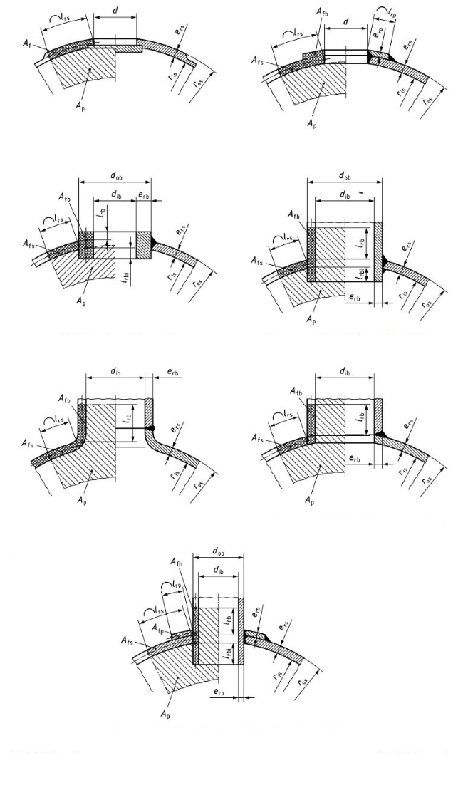
- Carry out the opening assessment: For manhole and nozzle openings, the weakening is captured via the opening factor; reinforcement is provided by an increased head wall thickness or a load-sharing nozzle wall thickness. Openings in the knuckle region are only permitted to a limited extent.
- Define allowances and final wall thickness: The undertolerance of the semi-finished product, the wear or corrosion allowance, and the fabrication-related thinning during flanging are added; the selected nominal wall thickness must cover the sum for all load cases.
Input quantities
| Quantity | Symbol | Unit |
|---|---|---|
| Temperature | T | °C |
| Calculation pressure | pc | MPa(p) |
| d2/ris | d2/ris | - |
| Weakening factor of end referring to branch 1 | v1 | - |
| Weakening factor of end referring to branch 2 | v2 | - |
| Existing mean stress of end referring to branch 1 | fa1 | N/mm² |
| Existing mean stress of end referring to branch 2 | fa2 | N/mm² |
| lrb2 | lrb | mm |
| erb2 | erb | mm |
| dib2 | dib | mm |
| dob2 | dob | mm |
| eb2 | eb | mm |
| Abzweigen | Abzweigen | – |
| Angle between two adjacent branches | Φb | ° |
| Arc dimension of Φb | rad(Φb) | - |
| zwei | zwei | – |
| b2 | c1, b | mm |
| b2 | c2, b | mm |
| fb2 | fb | N/mm² |
| kb2 | kb | N/mm² |
| sb2 | sb | - |
| Reference stress of knuckle | fk | N/mm² |
| Y-shaped branches | Y-förmig | – |
| Krempe | Krempe | – |
Calculation options
Y-shaped branches
No · Yes
Openings in end
without branch · Single branch · Adjacent branches
Type of end
Kloepperboden-type end · Korbbogen-type end · Elliptical end · Hemispherical end
Wall thickness transition according to Figure
Type a · Type b
Calculation according to section
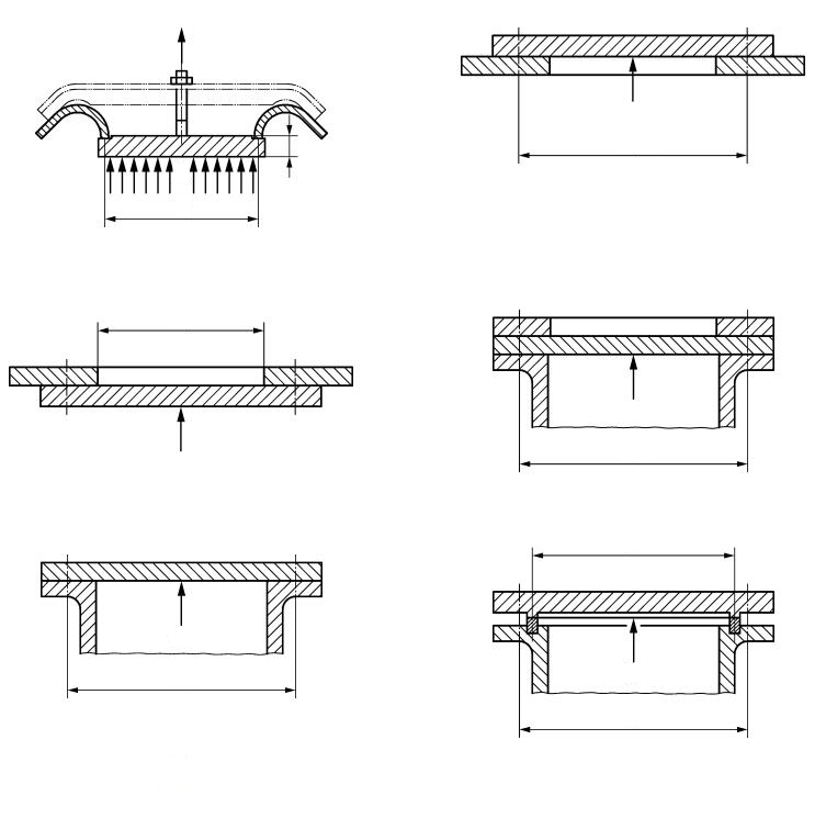
10.2 Spherical shells and dished ends · 10.3 Unstayed flat ends · 10.4 Flat unstayed closures
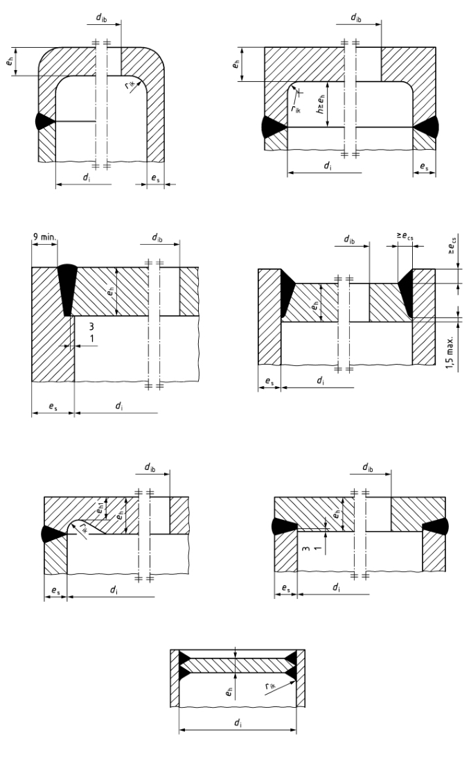
Type of first opening acc. fig. 10.2-6
1 · 2 · 3 · 4 · 5 · 6 · 7
Type of second opening acc. fig. 10.2-6
1 · 2 · 3 · 4 · 5 · 6 · 7
Type of flat end according image 10.3-1
1 · 2 · 3 · 4 · 5 · 6 · 7
Frequently asked questions
How does the head calculation to EN 12952-3 differ from that to EN 13445-3?
Both standards deal with dished ends, but EN 12952-3 is tailored to water-tube boilers: it works with its own safety factors, puts creep rupture strength at the forefront for design in the creep range, and governs the boiler-specific openings (manholes, tube stubs). For unfired pressure vessels, EN 13445-3 applies; the wall thicknesses from the two codes can differ noticeably for the same geometry.
Why is the knuckle often the governing location of the head?
In the knuckle, the meridional membrane force and the bending from the change of curvature between crown and straight flange are superimposed; in addition, the plate is thinned precisely there during flanging. This is why the knuckle check frequently yields the larger required wall thickness for Klöpper heads with their small knuckle radius, and openings in the knuckle region are particularly critical.
When must I calculate with the creep rupture strength instead of the elevated-temperature yield strength?
As soon as the design temperature lies within the creep range of the material (for ferritic boiler steels roughly above about 400–500 °C), the creep rupture strength referred to the planned service life becomes governing. EN 12952-3 then requires a comparison of both criteria; the smaller resulting allowable stress determines the wall thickness. For long service periods, additional creep-life monitoring to EN 12952-4 can be advisable.
Does the module also cover forces and moments from connected piping?
No. Clause 10 of EN 12952-3 explicitly sizes the heads for internal or external pressure only. External loads from piping, nozzle loads or support reactions must be investigated additionally, for example via local load assessments or a finite element analysis.