Engineering task and calculation objective
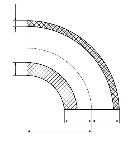
The WA11 module calculates the required wall thickness of pipes and pipe bends in water-tube boilers to Clause 11 of DIN EN 12952-3 — i.e. of evaporator, superheater and economizer tubes as well as connecting lines within the boiler. The basis is the mean-diameter formula for thin-walled pipes under internal pressure; for pipe bends, the pressure-related uneven distribution of the loading between the bend outside (extrados) and the bend inside (intrados) as well as the bending-related change in wall thickness are additionally taken into account.
In practice, this calculation is everyday work in the design and reassessment of boiler heating surfaces: to calculate pipe wall thickness to EN 12952-3, you need the material, the strength value at design temperature, the safety factor and, from these, the allowable stress; added to this are the allowance for the wall thickness undertolerance of the pipe (rolling tolerance) and the corrosion or wear allowance. At high tube wall temperatures in the superheater region, the creep rupture strength becomes the governing material property.
Since boiler tubes are installed in large quantities, every wall thickness optimization has a direct effect on weight, cost and heat transfer — a code-accurate calculation pays off twice here.
Standard and calculation basis: DIN EN 12952-3: 2023-01
Calculation workflow
- Determine material and allowable stress: From the material and the design temperature, the strength value is determined (elevated-temperature yield strength or, in the creep range, the creep rupture strength) and divided by the safety factor of the code; the result is the allowable stress f.
- Calculate wall thickness of the straight pipe: With the design pressure, pipe outside diameter and allowable stress, the mean-diameter formula of Clause 11 yields the required wall thickness of the straight pipe; for seamless pipes there is no weld joint reduction.
- Verify the pipe bend: For bends, the wall thickness is verified separately at the intrados and the extrados: on the bend inside, the circumferential stress is increased while bending simultaneously thickens the wall there; on the bend outside, the wall is thinned. The code provides radius-dependent factors for this.
- Add allowances: The allowance for the permissible wall thickness undertolerance to the pipe standard (e.g. a percentage rolling tolerance) and the corrosion/wear allowance are added to the calculated wall thickness; this yields the minimum ordering wall thickness.
- Select nominal wall thickness and document: From the minimum wall thickness, the nearest available standard wall thickness is selected; the utilization is documented for all load cases including test pressure.
Input quantities
| Quantity | Symbol | Unit |
|---|---|---|
| Temperature | TZ | – |
| Calculation pressure | pc | – |
| Material | – | – |
| Design strength | k | – |
| Safety factor | s | – |
| Allowable stress | f | – |
| Allowance for underrun of wall thickness of the cylindrical shell | c1 | – |
| Corrosion /wear allowance | c2 | – |
| Ordered wall thickness | e | – |
| Required wall thickness of straight tube with allowances | et | – |
| Outer diameter without allowances | do | – |
| Inner diameter without allowances | di | – |
| Weakening factor | v | – |
| Required wall thickness of tube without allowances | ect | – |
| Variable 22 | – | – |
| Minimum wall thickness | e-c1 | – |
| Existing thickness of the tube at the butt weld joint | eW | – |
| Minimum required thickness of the tube at the butt weld joint | eWt | – |
| Existing thickness of the tube at the axial force on the circular butt weld due to forces acting in addition to pressure | Q | – |
| Weld factor 1.0 for 100 % NDT and 0.85 for 10 % NDT | vZfP | – |
| Variable 29 | – | – |
| Required wall thickness of pipe bends and pipe elbows inner side with allowances | eti' | – |
| Required wall thickness of pipe bends and pipe elbows outer side with allowances | eto' | – |
| Required wall thickness of pipe bends and elbows inner side without allowances | eti | – |
Worked example
For a seamless, straight superheater tube of a water-tube boiler, the required wall thickness is to be determined to DIN EN 12952-3, Clause 11 — a worked example of a boiler tube wall thickness calculation. The allowable stress f has already been formed from the strength value and the safety factor.
Given values
| Design pressure pc | 8.0 MPa (80 bar) |
| Pipe outside diameter do | 38 mm |
| Allowable stress f | 123 N/mm² |
| Configuration | seamless, straight pipe (v = 1) |
| Allowance for wall thickness undertolerance c1 | 0.4 mm |
| Corrosion/wear allowance c2 | 1.0 mm |
Solution
Calculated wall thickness of the straight pipe
Using the mean-diameter formula for pipes under internal pressure (referred to the outside diameter):
ect = pc · do / (2 · f · v + pc)
ect = 8.0 · 38 / (2 · 123 · 1 + 8.0) = 304 / 254 = 1.20 mm
Minimum wall thickness with allowances
emin = ect + c1 + c2 = 1.20 + 0.4 + 1.0 = 2.60 mm
The nearest standard wall thickness of 2.9 mm is selected (tube 38 × 2.9).
Result
| Calculated wall thickness ect | 1.20 mm |
| Minimum wall thickness incl. allowances | 2.60 mm |
| Selected wall thickness | 2.9 mm |
All values are illustrative. The applicable standard and project-specific boundary conditions remain authoritative.
Frequently asked questions
Why does the bend inside govern for a pipe bend, even though the wall becomes thicker there during bending?
At the intrados, the pressure-related circumferential stress according to the torus solution is higher than in the straight pipe, because the same force must be transmitted over a smaller circumference. The thickening during bending partly compensates for this, but not necessarily completely — particularly for tight bend radii. The code therefore requires separate checks at the intrados and extrados: on the outside, bending thins the wall (typically governing in fabrication inspection); on the inside, the calculated required wall thickness is largest.
When do I calculate with the creep rupture strength?
As soon as the design wall temperature of the tube lies within the creep range — for unalloyed and low-alloy boiler steels roughly from 400–480 °C, correspondingly higher for martensitic 9% chromium steels. The governing value is then the creep rupture strength referred to the design life (e.g. 200,000 h) with the associated safety factor. For superheater tubes, moreover, the wall temperature, not the steam temperature, must be used — due to the heat flux it lies significantly above it.
What is the difference between the allowance for wall thickness undertolerance and the corrosion allowance?
The wall thickness undertolerance covers the permissible minus tolerance of pipe manufacturing (often a percentage for hot-rolled pipes, e.g. 12.5%) — it ensures that even the thinnest pipe delivered achieves the calculated wall thickness. The corrosion/wear allowance covers material loss during service (flue-gas-side corrosion, erosion). Both allowances are additive and must not be offset against each other.
Does Clause 11 also apply to downcomers and unheated connecting lines?
Yes, the formulas apply to heated and unheated pipes of the boiler; the difference lies in the applicable design temperature and, where relevant, in the allowance concept. For piping outside the boiler scope (steam lines to the turbine), however, EN 13480-3 must be applied.