Engineering task and calculation objective
The SUIP module sizes the pressure-bearing primary components of a vessel or tank to DIN EN 13445-3 and DIN EN 14025: cylindrical shells, spherical shells and conical shells under internal pressure, as well as dished ends (Klöpper/torispherical, Korbbogen/deep torispherical and elliptical heads) under internal and external pressure. A particular focus is the cone-cylinder junction — the transition between the conical and cylindrical shell sections, where the redirection of the membrane forces generates additional bending stresses and local reinforcement is frequently required.
In practice, this calculation is needed for every design of pressure vessels, columns, silos with conical outlets or tank containers: to calculate wall thickness to EN 13445, you determine the required wall thickness of each shell element from the design pressure, the nominal design stress and the joint efficiency, and then verify the transitions. The inclusion of DIN EN 14025 also makes the module applicable to tanks for the transport of dangerous goods (rail tank wagons, road tankers).
The head-type selection allows all common head geometries to be handled in a single calculation run, so that variants (e.g. torispherical Klöpper head versus Korbbogen head) can be compared quickly.
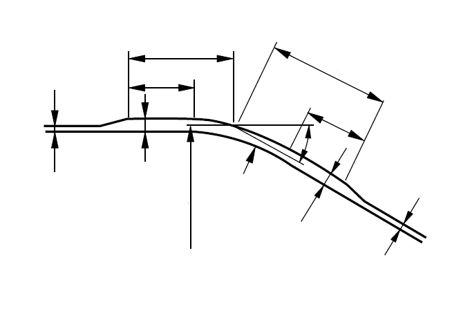
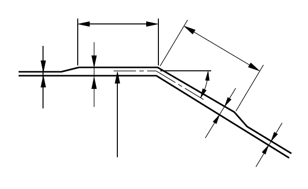
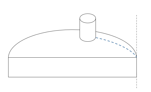
Standard and calculation basis: DIN EN 13445-3/7: 2021-12 & DIN EN 14025: 2018-09
Calculation scope
- Cone-cylinder intersections under internal pressure
- Cylindrical shells under internal pressure
- Spherical shells under internal pressure
- Kloepper type heads under internal and external pressure
- Korbbogen type heads under internal and external pressure
- Elliptical Heads under internal and external pressure
- Conical shells under internal pressure
Calculation workflow
- Define geometry and head type: First, the component geometry is selected: cylindrical, spherical or conical shell, or — via the head-type selection — Klöpper (torispherical), Korbbogen (deep torispherical) or elliptical head. Diameter, cone half-angle and knuckle radii determine which equations of EN 13445-3 (Clause 7) govern.
- Determine design pressure and allowable stress: From the design pressure and design temperature together with the material, the nominal design stress f is determined in accordance with EN 13445-3 Clause 6 (minimum of the yield-strength and tensile-strength criteria). The joint efficiency z follows from the testing group of the longitudinal welds.
- Calculate required wall thicknesses of the shell sections: For the cylindrical, spherical and conical shells, the required wall thickness is calculated from the membrane stress equations of the code; for dished ends, the checks against plastic failure of the knuckle and against elastic-plastic buckling of the crown are added, and for external pressure the stability checks of Clause 8 apply.
- Verify the cone-cylinder junction: At the cone-cylinder junction (large and small end), it is checked whether the actual wall thicknesses can carry the local bending and membrane stresses; if necessary, a reinforced transition zone or a knuckle with a transition radius becomes necessary.
- Allowances and final wall thickness: The corrosion or wear allowance and the permissible undertolerance of the semi-finished product are added to the required wall thickness; the selected nominal wall thickness must cover the sum. Finally, the utilization is documented for all load cases (operation, testing).
Input quantities
| Quantity | Symbol | Unit |
|---|---|---|
| Load case | 2=Prüfung) | – |
| Calculation temperature | t | °C |
| Calculation pressure | P | MPa |
| Material designation | Werkstoffbezeichnung | – |
| Wall thinning allowance | δe | mm |
| Corrosion allowance | c | mm |
| Thinning allowance during manufacturing | δm | mm |
| Sum of allowances | ∑(δ) | mm |
| Material strength | (Re, Rp, Rm) K | MPa |
| Safety factor | S | – |
| Strength condition | Festigkeitsbedingung | – |
| Nominal design stress | = Min[0.5·Rm20; 0.75·Rpe] f | MPa |
| Nominal wall thickness | en | mm |
| Material strength | (Re, Rp, Rm) K | MPa |
| Safety factor | S | – |
| Material strength | (Re, Rp, Rm) K | MPa |
| Safety factor | S | – |
| Required thickness | e | mm |
| Weld factor | z | – |
| Analysis thickness | en - ∑(δ) ea | mm |
| Mean diameter | Dm | mm |
| Outside diameter | De | mm |
| Maximum allowable pressure | Pmax | MPa |
| Geometrical conditions | Bedingungen | – |
Calculated results
| Quantity | Symbol | Unit |
|---|---|---|
| Load case | 2=Prüfung) | – |
| Strength condition | Festigkeitsbedingung | – |
| Inside diameter | Di | mm |
| Required thickness | e | mm |
| Analysis thickness | en - ∑(δ) ea | mm |
| Mean diameter | Dm | mm |
| Maximum allowable pressure | Pmax | MPa |
| Geometrical ratio | e/De | – |
| Geometrical conditions | Bedingungen | – |
| Inside radius of knuckle | r | mm |
| Inside radius of spherical part | R | mm |
| Parameter | Y = Z = X = N = | – |
| Parameter | Y = Z = X = N = | – |
| Parameter | Y = Z = X = N = | – |
| Parameter | Y = Z = X = N = | – |
| Calculation coefficient | β | – |
| Parameter | β0.06 = β0.1 = β0.2 = | – |
| Parameter | β0.06 = β0.1 = β0.2 = | – |
| Parameter | β0.06 = β0.1 = β0.2 = | – |
| Required thickness of spherical part, membrane | es | mm |
| Required thickness of knuckle, yield | 7.5.3.5 ey | mm |
| Required thickness of knuckle, plastic buckling | eb | mm |
| Geometrical ratio | R/De | – |
| Geometrical ratio | r/De | – |
Calculation options
Regulation
EN 13445-3: Unfired pressure vessels · EN 14025: Tanks for the transport of dangerous goods
Condition satisfied
No · Yes
Selection type of head
Cylindrical shells under internal pressure · Spherical shells under internal pressure · Kloepper type · Korbbogenboden type · Ellipsoidal ends · Conical shells · Junction between large end of cone and cylinder without knuckle · Junction between large end of cone and cylinder with knuckle · Junction between small end of cone and cylinder
Worked example
For a vessel to DIN EN 13445-3, the required wall thickness of the cylindrical shell under internal pressure is to be determined — a typical worked example of a pressure vessel calculation. The nominal design stress f has already been determined from the material properties.
Given values
| Design pressure P | 1.6 MPa (16 bar) |
| Inside diameter Di | 1,200 mm |
| Nominal design stress f | 147 N/mm² |
| Joint efficiency z | 0.85 (testing group 3) |
Solution
Required wall thickness to EN 13445-3, Eq. (7.4-1)
For cylindrical shells under internal pressure:
e = P · Di / (2 · f · z − P)
e = 1.6 · 1,200 / (2 · 147 · 0.85 − 1.6) = 1,920 / 248.3 = 7.73 mm
Allowances and wall thickness selection
The corrosion allowance c and the permissible minus tolerance of the plate must be added to the required wall thickness. With c = 1 mm and a plate tolerance of 0.3 mm, the minimum nominal wall thickness is 7.73 + 1 + 0.3 = 9.03 mm; a nominal thickness of en = 10 mm is selected.
Result
| Required wall thickness e | 7.73 mm |
| Selected nominal wall thickness en | 10 mm |
All values are illustrative. The applicable standard and project-specific boundary conditions remain authoritative.
Frequently asked questions
Why is the cone-cylinder junction often thicker than the cone and the cylinder themselves?
At the junction the shell mid-surface changes direction, and the meridional force has to be redirected. This generates additional circumferential compressive forces and local bending stresses that a pure membrane calculation does not cover. EN 13445-3 therefore requires a dedicated check of the junction zone, which frequently results in a larger wall thickness over a defined region on both sides of the junction — particularly for large cone half-angles and for junctions without a knuckle.
When does DIN EN 14025 apply in addition?
DIN EN 14025 governs metallic pressure tanks for the transport of dangerous goods (RID/ADR), i.e. rail tank wagons and road tankers. For the strength calculation it largely refers to EN 13445-3, but it defines its own minimum wall thicknesses, design pressures and dynamic loads arising from transport. For stationary pressure vessels, EN 13445 alone governs.
What is the difference between Klöpper, Korbbogen and elliptical heads in the calculation?
All three are treated as dished ends in EN 13445-3 but differ in crown and knuckle radius: the Klöpper (torispherical) head (R = Da, r = 0.1·Da) has the sharper knuckle and usually yields the largest required wall thickness at the same pressure; the Korbbogen (deep torispherical) head (R = 0.8·Da, r = 0.154·Da) is more favourable but has a greater overall height. Elliptical heads are reduced to the torisphere via equivalent radii. The governing value is always the maximum of the membrane, knuckle-plastification and buckling checks.
Does the module also cover external pressure?
For the dished ends (Klöpper, Korbbogen and elliptical heads) yes — here the stability check against buckling is included. Cylindrical and conical shells are treated in SUIP under internal pressure; for cylinders under external pressure (buckling between stiffeners), the checks to EN 13445-3 Clause 8 are carried out in separate modules.