Engineering task and calculation objective
The CYCL module sizes centrifugal separators (cyclones) for gas-solid separation. From the gas properties (density, dynamic viscosity), the solids data (solid density, bulk density, void fraction of the bed) and the operating data (volume or mass flow, inlet velocity, inlet dust load), it calculates the two central design quantities of a cyclone: the total pressure drop and the separation efficiency.
The pressure drop is broken down into its physical components – guide vane duct or inlet, separation chamber and vortex finder (immersion tube) – so you can see which part of the geometry causes the greatest resistance. For the separation performance, the module determines the cut size (limiting particle diameter) of the cyclone and, from the particle size distribution of the feed (median particle size and slope parameter of the residue curve, e.g. per RRSB), derives the inner and total separation efficiency, including limiting-load effects at high dust concentrations.
In practice, this calculation is needed wherever dust must be removed from process gases: in dedusting downstream of dryers, mills and fluidized beds, as a pre-separator upstream of filters, or in pneumatic conveying. If you want to calculate a cyclone separator, CYCL delivers pressure drop and separation efficiency in a single run, so geometry variants can be compared quickly.
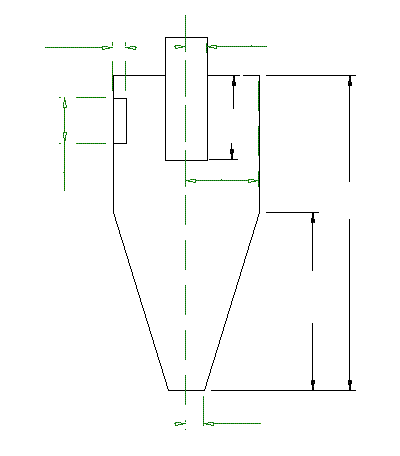
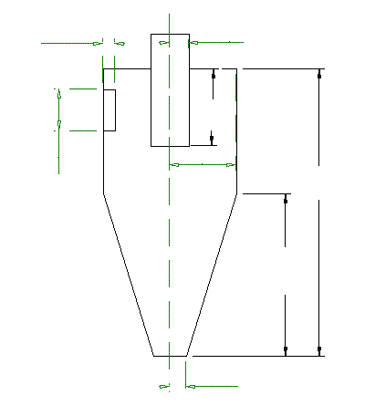
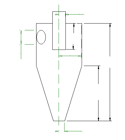
Calculation workflow
- Define gas and solids data: First, the properties of the carrier gas (density and dynamic viscosity at operating conditions) are entered together with the solids data (solid density, bulk density, void fraction of the bed) and the particle shape factor. These determine the settling velocity of the particles in the centrifugal field.
- Define the operating point: The gas volume flow or mass flow, the inlet velocity and the inlet dust load (mass- or volume-based) fix the operating point. Optionally, a friction factor for pure gas can be specified; otherwise the module uses the default value of the calculation method.
- Characterize the feed material: The particle size distribution of the feed is described by the median particle size and the slope parameter of the residue curve; alternatively, a single particle with a defined diameter can be considered. Together with the constant for the limiting load, this captures the saltation-load effect at high dust concentrations.
- Calculate the pressure drop: The module determines the partial pressure drops in the guide vane duct or inlet, in the separation chamber and in the vortex finder, and sums them to the total pressure drop. The fraction of secondary flow is included in the flow balance.
- Determine cut size and separation efficiency: The cut size of the cyclone follows from the force balance between centrifugal force and drag. Using the grade efficiency curve and the particle size distribution of the feed, the module calculates the inner separation efficiency and – taking the limiting load into account – the total separation efficiency and the residual dust load (mass and volume load) at the outlet.
Input quantities
| Quantity | Symbol | Unit |
|---|---|---|
| Type of cyclone inlet | – | – |
| Cyclone Type | – | – |
| Total height of cyclone | h | – |
| Length of immersion tube | hT | – |
| Cone height of cyclone | hk | – |
| Outside radius of cyclone | ra | – |
| Radius of immersion tube / inside radius | ri | – |
| Radius of lower cone opening | r3 | – |
| Angle of inclination of cone | εk | – |
| Inlet height or diameter | he/d | – |
| Inlet width | b | – |
| Relative wall roughness | ks/ra | – |
| Constant for limiting load | KG | – |
| Medium doplet size of feed or diameter of current droplet Input required for one-size doplet feed only | d50,A | – |
| Parameter of inclination of residual curve of feed | nA | – |
| limiting droplet diameter | DFakt | – |
| Shape factor of droplet | FKorn | – |
| Friction factor of pure gas Optional input | λ0 | – |
| Load at inlet (Mass) | μe | – |
| Density of solid | ρs | – |
| Void fraction of bed of solids | εs | – |
| Density of gas | ρL | – |
| Inlet velocity | υe | – |
| Volume flow of gas | V | – |
Calculated results
| Quantity | Symbol | Unit |
|---|---|---|
| Fraction of secondary flow | VpSek | – |
| Pressure drop guide vane duct | dPek | – |
| Pressure drop separation area | dPe | – |
| Pressure drop immersion tube | dPi | – |
| Total pressure drop | dPges | – |
Calculation options
Type of cyclone inlet
1 · 2 · 3 · 4
Cyclone Type
1 · 2
Variable 40
1 · 2 · 3 · 4
Feed
1 · 2 · 3
Type of guide vanes Input required for type 4 only
0 · 1 · 2 · 3
Frequently asked questions
What does the cut size of a cyclone mean?
The cut size (cut-point diameter) is the particle diameter at which centrifugal force and drag are exactly in balance within the vortex. Particles well above the cut size are separated almost completely, while significantly smaller ones are mostly carried out with the gas. The real separation behavior is not a step function, however, but a grade efficiency curve around the cut size – which is why the total separation efficiency is always integrated over the particle size distribution of the feed.
Why does the separation efficiency increase at high inlet dust loads?
Above a limiting load, the flow can no longer keep the dust fully suspended; part of the solids is deflected to the wall as a strand right at the inlet and runs directly into the hopper. Only the remaining load is subject to the actual centrifugal separation in the inner vortex. This effect is captured by the constant for the limiting load and means that cyclones at high dust concentrations separate better overall than the grade efficiency curve alone would suggest.
What role does the vortex finder play in the pressure drop?
The vortex finder (immersion tube) is usually the single largest contributor to the pressure drop, because that is where the high tangential velocity of the inner vortex is redirected into the outlet and dissipated. A smaller vortex finder diameter improves the cut size (higher tangential velocity) but increases the pressure drop disproportionately. By reporting the partial pressure drops separately, the module makes this trade-off between separation performance and energy demand visible.
How is the particle size distribution of the feed described?
By the median particle size and the slope parameter of the residue curve, corresponding to the RRSB representation (Rosin-Rammler-Sperling-Bennett). The median particle size gives the position, the slope parameter the width of the distribution: a narrow collective (large slope parameter) leads to a sharp separation, while a broad collective contains many fines that even a well-designed cyclone cannot separate. For monodisperse cases, a single particle with a fixed diameter can be calculated instead.