Engineering task and calculation objective
The EC3Cyl module performs the stability and strength verification for cylindrical shells to DIN EN 1993-1-6 (Eurocode 3, shell structures). For thin-walled cylinders under axial compression, external pressure or vacuum, or shear, buckling is the governing failure mode – typical applications are silos, storage tanks, chimneys and vessel skirts. Through the extension to DIN EN 1993-4-1, complete silos and tank structures can be calculated, including the actions from bulk solids, wind and imposed loads; the module thereby replaces the former 18T4 module based on the withdrawn DIN 18800-4.
Calculating a shell buckling verification to EN 1993-1-6 means: for each type of loading, the elastic critical buckling stress, the imperfection reduction factor as a function of the fabrication tolerance quality class, and from these – via the relative slenderness – the buckling reduction factor are determined. The design value of the buckling resistance is then compared with the acting stress, and the interaction of simultaneously acting stress components is checked.
Since the Eurocode standards primarily cover non-alloy structural steels, the module has additionally been extended to stainless steels up to 500 °C – important for heated equipment and vessel construction in the process industries.
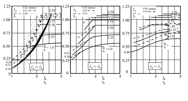
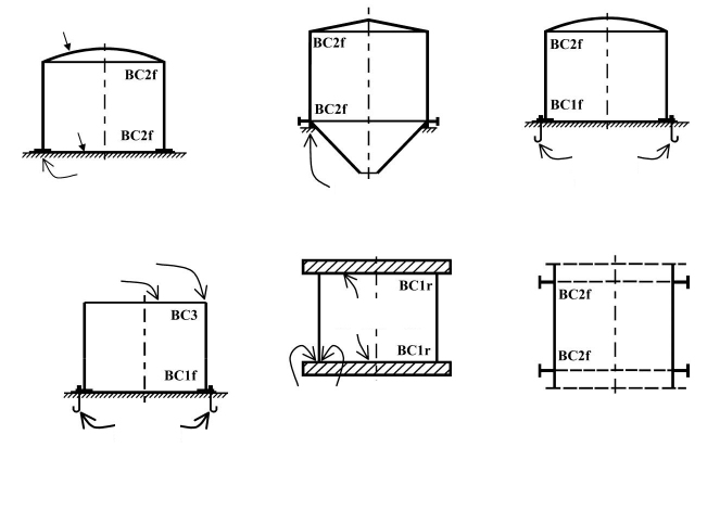
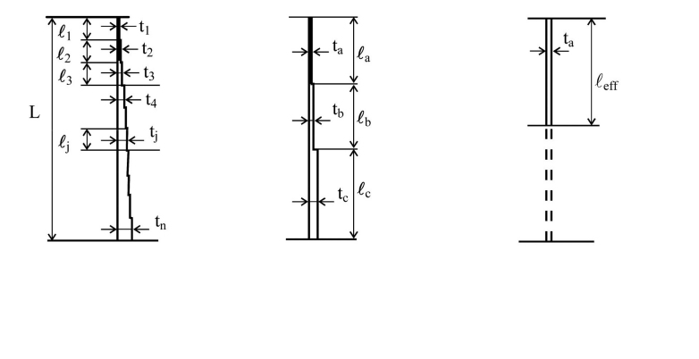
Standard and calculation basis: DIN EN 1993-1-6: 2017-07 (Eurocode 3)
Calculation workflow
- Define geometry, material and tolerance class: The inputs are the radius, wall thickness and length of the shell segment (or of the segments between ring stiffeners), the yield strength of the material at design temperature, and the fabrication tolerance quality class A, B or C, which determines the imperfection sensitivity.
- Determine the acting membrane stresses: From dead weight, superstructures, imposed loads, wind, vacuum and, where applicable, bulk solids loads per EN 1993-4-1, the meridional, circumferential and shear membrane stresses in the governing section are calculated.
- Calculate the elastic critical buckling stresses: For axial compression, circumferential compression and shear, the elastic critical buckling stresses are determined – depending on the length range (short, medium-length or long cylinder) via the dimensionless length parameter.
- Determine reduction factors and buckling resistance: From the characteristic imperfection amplitude of the tolerance class follows the imperfection reduction factor; from the ratio of yield strength to elastic critical buckling stress, the relative slenderness. The buckling curve yields the buckling reduction factor, and with the partial safety factor, the design value of the buckling resistance.
- Check individual verifications and interaction: Each stress component is compared with its buckling resistance; the interaction condition for simultaneously acting axial compression, circumferential compression and shear is then evaluated. The plastic limit states (equivalent stress check) are performed in addition. The equations used can be displayed for documentation.
Input quantities
| Quantity | Symbol | Unit |
|---|---|---|
| Number of cylindrical sections from top to bottom | Azyl | – |
| Outside diameter of shell | dac | m |
| Wall thickness | tc | mm |
| Length | lc | mm |
| Wall thickness | tc | mm |
| Length | lc | mm |
| Wall thickness | tc | mm |
| Length | lc | mm |
| Wall thickness | tc | mm |
| Length | lc | mm |
| Show equations? | anzeigen | – |
| Filling level of cylindrical shell | Hc | mm |
| Material of cylindrical shell (carbon steel only) | WkNrS | – |
| Metal temperature | 1993-1-6, 1.1 T | °C |
| Modulus of elasticity | E | N/mm² |
| Material charecteristic (yield strength) | 1993-1-6, 3.1 fyk | N/mm² |
| Density of material | ρc | kg/dm³ |
| Gravity | g | m/s² |
| Filling medium | Füllmedium | – |
| Density of filling medium | ρf | kg/m³ |
| Metal temperature | 1993-1-6, 1.1 | – |
| Microstructure | Werkstoffs | – |
| Type of silo roof | roof | – |
| Self weight of roof and attachments | Gd | kN |
Calculated results
| Quantity | Symbol | Unit |
|---|---|---|
| Total length of shell | L | mm |
| Mean diameter of shell | dm | m |
| Inside diameter | dic | m |
| Inside diameter | dic | m |
| Inside diameter | dic | m |
| Inside diameter | dic | m |
| Shell center radius | rmc | m |
| Average thickness of complete shell | tmc | mm |
| Condition radius/thickness | 1993-1-6, 1.1 | – |
| Shell center circumference | Ui | m |
| Filling cross-section | Ai | m² |
| Metallic cross section | Amet | m² |
| Metallic cross section | Amet | m² |
| Metallic cross section | Amet | m² |
| Metallic cross section | Amet | m² |
| Nominal volume | Vnom | m³ |
| Nominal volume | Vnom | m³ |
| Nominal volume | Vnom | m³ |
| Nominal volume | Vnom | m³ |
| Total nominal value | Vnom | m³ |
| Maximum volume in cylindrical shell | Vmax | m³ |
| Self weight of shell | Gc | kN |
| Self weight of shell | Gc | kN |
| Self weight of shell | Gc | kN |
Calculation options
Type of silo roof
closed · small opening · completely open
Case distinction Table D.1
Case 1 · Case 2 · Case 3
Case distinction Table D.2
excellent · high · normal
Consider internal pressure?
do not consider · consider
Case distinction Table D.5
excellent · high · normal
Case distinction Table D.1
Case 1 · Case 2 · Case 3
Case distinction Table D.1
Case 1 · Case 2 · Case 3
Case distinction Table D.1
Case 1 · Case 2 · Case 3
Worked example
For the shell course of a tank structure made of S235, the design value of the axial buckling resistance to DIN EN 1993-1-6 is to be determined as a worked example. The course between two ring stiffeners has radius r = 1,000 mm, wall thickness t = 10 mm and length l = 4,000 mm. Fabrication tolerance quality class B, partial safety factor γM1 = 1.1.
Given values
| Radius r | 1,000 mm |
| Wall thickness t | 10 mm |
| Length between ring stiffeners l | 4,000 mm |
| Yield strength fyk (S235) | 235 N/mm² |
| Modulus of elasticity E | 210,000 N/mm² |
| Tolerance class | B (Q = 25) |
| Partial safety factor γM1 | 1.1 |
Solution
Check the length range
Dimensionless length parameter:
ω = l / √(r · t) = 4,000 / √(1,000 · 10) = 4,000 / 100 = 40
Medium-length cylinder, since 1.7 ≤ 40 ≤ 0.5 · r/t = 50. Hence the factor Cx = 1.0 applies.
Elastic critical axial buckling stress
σx,Rcr = 0.605 · Cx · E · t / r = 0.605 · 1.0 · 210,000 · 10 / 1,000 = 1,270.5 N/mm²
Imperfection reduction factor (class B)
Characteristic imperfection amplitude:
Δwk = (1/Q) · √(r/t) · t = (1/25) · √(100) · 10 = 4.0 mm, hence Δwk/t = 0.4
αx = 0.62 / (1 + 1.91 · (Δwk/t)1.44) = 0.62 / (1 + 1.91 · 0.267) = 0.62 / 1.510 = 0.410
Relative slenderness and buckling reduction factor
Relative slenderness:
λ̄x = √(fyk / σx,Rcr) = √(235 / 1,270.5) = 0.430
Plastic limit relative slenderness (with β = 0.6):
λ̄p = √(αx / (1 − β)) = √(0.410 / 0.4) = 1.013
Since λ̄0 = 0.2 < 0.430 < 1.013, elastic-plastic buckling governs (interpolation range, η = 1.0):
χx = 1 − β · ((λ̄x − λ̄0) / (λ̄p − λ̄0))η = 1 − 0.6 · (0.230 / 0.813) = 0.830
Design value of the buckling resistance
Characteristic buckling stress:
σx,Rk = χx · fyk = 0.830 · 235 = 195.1 N/mm²
Design value:
σx,Rd = σx,Rk / γM1 = 195.1 / 1.1 = 177.4 N/mm²
The acting meridional compressive stress from dead weight, superstructures and wind must not exceed this value.
Result
| Elastic critical axial buckling stress σx,Rcr | 1,270.5 N/mm² |
| Imperfection reduction factor αx | 0.410 |
| Buckling reduction factor χx | 0.830 |
| Design value of the axial buckling resistance σx,Rd | 177.4 N/mm² |
All values are illustrative. The applicable standard and project-specific boundary conditions remain authoritative.
Frequently asked questions
What does the fabrication tolerance quality class mean, and how strongly does it influence the result?
EN 1993-1-6 distinguishes classes A (excellent), B (high) and C (normal), defined by permissible dimple, out-of-roundness and misalignment tolerances. The class enters directly into the characteristic imperfection amplitude and thus into the imperfection reduction factor. Between class A and class C the axial buckling resistance can vary by several tens of percent – the class must actually be demonstrated in fabrication and must not merely be assumed in the calculation.
Why does EC3Cyl replace the 18T4 module to DIN 18800-4?
DIN 18800-4 (buckling verification of shells) was withdrawn with the transition to the Eurocodes; the successor code is DIN EN 1993-1-6 with its National Annex, supplemented by DIN EN 1993-4-1 for silos and tanks. For new designs the Eurocode governs; re-analyses of existing structures to DIN 18800-4 remain relevant for putting historical designs into context.
May I also verify stainless steel shells at elevated temperature with the module?
The Eurocode parts 1993-1-6 and 1993-4-1 are primarily formulated for non-alloy structural steels. The module extends the scope to stainless steels up to 500 °C by applying temperature-dependent material properties (yield strength, modulus of elasticity). Note, however, that the National Annex or the building authority approval does not always explicitly cover such extensions – in projects subject to building control this must be agreed with the checking engineer.
What is the difference between the buckling verification to EN 1993-1-6 and the one to EN 13445-3?
EN 13445-3 (pressure vessels) addresses stability mainly for external pressure in Chapter 8, with its own safety concepts for pressure equipment. EN 1993-1-6 is the structural design code for shell structures and covers axial compression, wind, shear and combinations with the partial safety concept of the Eurocode. Silos and tanks as building structures fall under the Eurocode; pressure vessels under the Pressure Equipment Directive with EN 13445 – this classification decides which code applies.