Engineering task and calculation objective
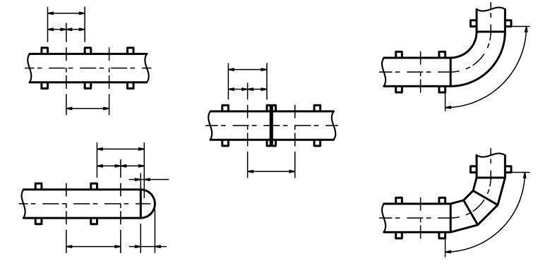
Piping that is operated under vacuum, fitted with a heating jacket, or surrounded by a higher external pressure does not fail by bursting but by buckling inward. This module performs the stability verification for piping components under external pressure to DIN EN 13480-3, clause 9: cylindrical pipes, pipe bends and elbows, reducers (as conical shells), and dished ends.
The verification against buckling differs fundamentally from the internal pressure calculation: what governs is not only the allowable stress of the material but above all the modulus of elasticity, the slenderness of the shell (ratio of diameter to wall thickness and unstiffened length) and shape deviations such as out-of-roundness. Even small initial imperfections significantly reduce the actual collapse pressure, which is why the code sets limits on ovality and works with separate safety factors against elastic and plastic failure.
Typical applications in plant engineering are vacuum lines, suction lines with possible negative pressure during draining, double-walled lines with a pressurized annulus, and condensation cases in which a steam system is suddenly pulled into vacuum. If you need to calculate a pipe under external pressure, this module delivers the complete verification to DIN EN 13480-3.
Standard and calculation basis: DIN EN 13480-3/9: 2017-12
Calculation scope
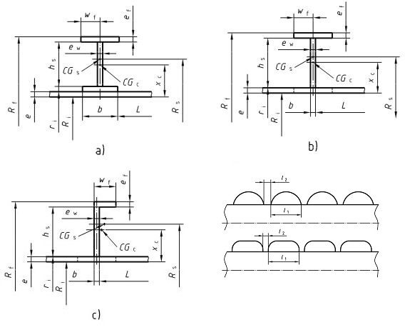
- Cylindrical pipes, elbows and mitre bends under external pressure
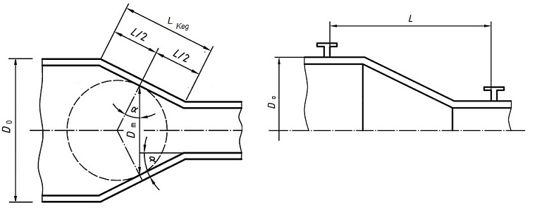
- Reducers under external pressure
- Dished ends under external pressure
Calculation workflow
- Define component and geometry: First, the component to be verified is selected: straight pipe, pipe bend or elbow, reducer, or dished end. The inputs are diameter, wall thickness minus allowances, the unstiffened length between effective stiffeners (flanges, heads, rings), and for bends the bend radius and the actual ovality.
- Determine material properties at design temperature: The stability verification requires the modulus of elasticity and the yield strength at design temperature. Both properties decrease with temperature, which directly reduces the allowable external pressure — for austenitic steels the different material behaviour must additionally be taken into account.
- Determine the failure limits: The module calculates the two governing limits: the pressure at which the circumferential stress reaches the yield strength (plastic failure), and the theoretical elastic buckling pressure of the shell, which depends on the modulus of elasticity, the wall-thickness-to-radius ratio, the unstiffened length and the associated circumferential wave number of the buckling mode.
- Derive the allowable external pressure: From the interaction of both limits, the sustainable pressure is determined via the buckling curve of the code and reduced by the prescribed safety factors. For reducers, the verification is carried out on the equivalent cylinder of the conical shell; for dished ends, on the spherical portion.
- Check shape tolerances: Finally, it is checked whether the actual out-of-roundness of the component lies within the limits assumed by the code. Greater ovality — for instance in bends resulting from the bending process — reduces the allowable external pressure and must be explicitly accounted for in the verification.
Input quantities
| Quantity | Symbol | Unit |
|---|---|---|
| Elastic limit | S | N/mm² |
| Nominal design strength | Rp0,2t | N/mm² |
| Elastic limit | SS | N/mm² |
| Nominal design strength | Rp0,2St | N/mm² |
| Mean radius of the cylindrical pipe | Rm | mm |
| Modulus of elasticity | Et | N/mm² |
| Modulus of elasticity | EtS | N/mm² |
| Length of conical shell for calculation of the moment of inertia | LIx | mm |
| Analysis wall thickness | ea | mm |
| Poisson's ratio | ν | – |
| Axial length between effective stiffeners | L | mm |
| Mean inter-stiffener distance Figure 9.3.1-1 | Lc | mm |
| Momemt of inertia of combined cross sectional area | Ic | mm^4 |
| Radius to the part of the channel with the greatest distance to the pipe | Rf | mm |
| Required external design pressure | p | MPa |
| Cross sectional area of stiffener | As | mm² |
| Radius of centroid of cross sectional area | Rs | mm |
| Cross sectional area of stiffener plus effective pipe length | Ae | mm² |
| Radial height | hs | mm |
| Analysis wall thickness | eaw | mm |
| Analysis wall thickness | eaf | mm |
| Radius of the point of the channel which is closest to the pipe assumed as pivot point | ri | mm |
| Projection width of stiffening flange | wf | mm |
| Effective pipe length | lps | mm |
Calculated results
| Quantity | Symbol | Unit |
|---|---|---|
| Pressure at yield point of material | py | MPa |
| Theoretical elastic buckling pressure at collapse of an exactly cylindrical pipe | pm | MPa |
| Calculated lower collapse pressure | pr | MPa |
| Ratio pm / py | Vpm/py | - |
| Ratio pr / py | Vpr/py | - |
| Mean elastic circumferential strain at collapse | ε | mm |
| Number of buckling corrugations in cirumferential direction in the unstiffened part of the cylinder | ncyl | – |
| Section modulus of pipe | Z | – |
| Safety factor | k | – |
| Theoretical elastic buckling pressure of stiffened cylinder | pn | MPa |
| Factor depending on the fabrication of stiffener | ks | – |
| Pressure which leads to yield in circumferential direction | pys | MPa |
| Maximum stress in a heavy stiffening | σs | MPa |
| Buckling stress at which the stiffener is laterally deflected | σi | MPa |
| \u03b4 | δ | - |
| Number of buckling corrugations in cirumferential direction in the stiffened cylinder | n | – |
| Xc | Xc | – |
| \u03bb | λ | – |
| C\u03c3i | Cσi | – |
| Ratio hs / ew | Vhs/ew | - |
| Ratio wf / ef | Vwf/ef | - |
| Ratio hs/Rm | Vhs/Rm | - |
| Geometrical condition | hs/ew | – |
| Geometrical condition | wf/ef | – |
Calculation options
Stiffening made of cast steel
No · Yes
Forming method of the stiffening
Hot-rolled stiffening · Cold-rolled stiffening
Cross sectional shape of the stiffening
Rectangular · Non-rectangular · Heating / Cooling Channel
Type of stiffening according to figure
0 · 1 · 2 · Heating / Cooling Channel
Type of stiffening
Internal stiffening · External stiffening · No stiffening
Type of end
Hemispherical ends · Kloepper type · Ellipsoidal ends · Korbbogen type
Type
9.3 Cylindrical pipes, elbows and mitre bends · 9.4 Reducers (conical pipes) · 9.5 Dished ends
Frequently asked questions
Why is it not enough to simply treat external pressure like a negative internal pressure?
Under internal pressure, the strength of the material limits the load capacity; under external pressure it is the stability of the shell. A thin-walled pipe can buckle elastically far below the yield strength; the governing quantities are then the modulus of elasticity, the geometry and the initial imperfections rather than the allowable stress. That is why DIN EN 13480-3 requires a separate verification to clause 9 with its own safety factors.
What role does the unstiffened length play and how can I shorten it?
The longer the unstiffened section, the lower the elastic buckling pressure, because long-wave buckling modes with a small circumferential wave number can develop. Effective stiffeners are flanges, heads and welded-on stiffening rings of sufficient bending stiffness. By placing stiffening rings at regular intervals, the allowable external pressure can be increased significantly without increasing the wall thickness.
Why is out-of-roundness so critical in the external pressure verification?
An oval shell no longer carries the external pressure as a pure circumferential compression membrane, but experiences additional bending stresses that initiate buckling. Even a few percent ovality can reduce the sustainable pressure considerably. The code therefore assumes a maximum out-of-roundness; particularly for induction-bent or cold-bent pipe bends, the actual ovality must be measured and applied in the verification.
Must a line that can only fall under vacuum in an upset condition be designed for external pressure?
Yes, if the negative pressure is not reliably prevented. Typical cases are the draining of closed systems, condensing steam after shutdown, or failure of a venting device. It is common practice to design for full vacuum (1 bar external pressure) unless a reliable vacuum breaker is in place — the decision is part of the plant's safety assessment.