Engineering task and calculation objective
Pipe ends, header ends and manifold closures must be designed just as safely as the pipes themselves. This module calculates heads (ends) for metallic industrial piping to DIN EN 13480-3, clause 7: hemispherical heads, torispherical heads (Klöpper and Korbbogen types), ellipsoidal heads, and flat circular ends — welded or bolted — each under internal pressure. The reinforcement of openings in unstayed flat ends is also covered.
In practice, this calculation is needed whenever a piping system, a header or a manifold is closed off with an end and the required wall thickness or the allowable pressure must be verified to the European piping code. The design type is selected via a type switch; the module then applies the governing equations of clause 7 — for dished heads separately for crown and knuckle, for flat ends with the design-dependent calculation coefficients.
If you want to calculate a torispherical head — a Klöpper head or Korbbogen head — this worked approach gives you the minimum wall thickness of all head regions, so you can directly check the selected nominal wall thickness, including allowances, against the requirements of DIN EN 13480-3.
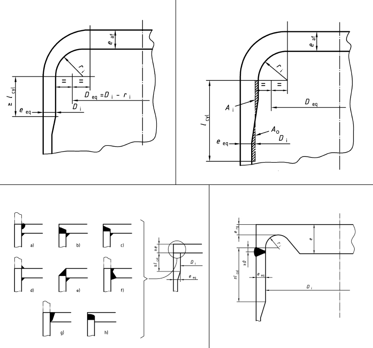
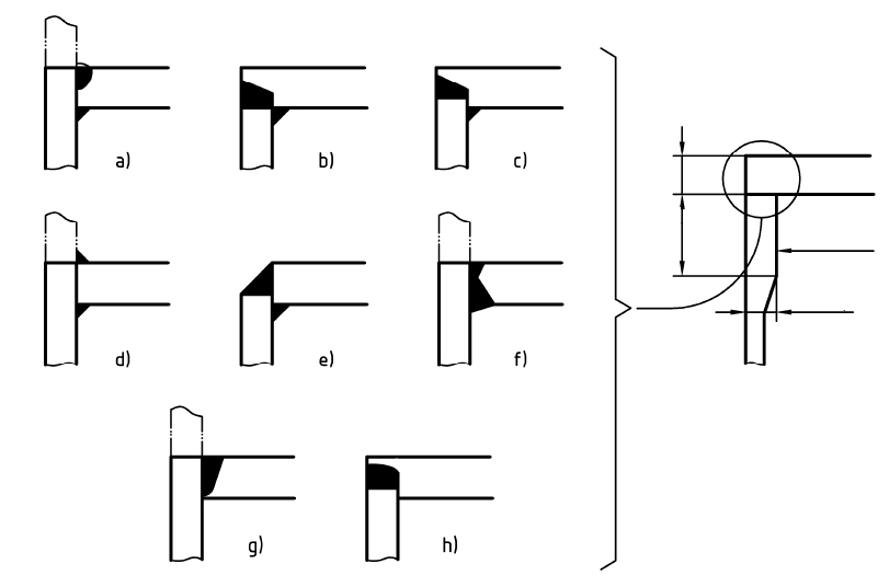
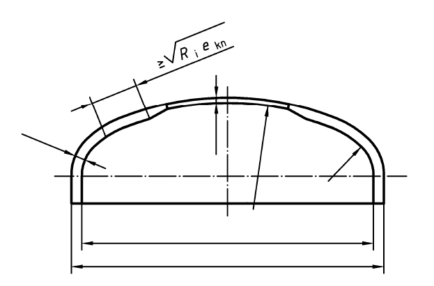
Standard and calculation basis: DIN EN 13480-3/7: 2017-12
Calculation scope
- Elliptical heads under internal pressure
- Unstayed flat circular ends welded to cylindrical shells/pipes under internal pressure
- Unstayed flat circular bolted ends under internal pressure
- Reinforcement of openings in unstayed flat ends under internal pressure
- Hemispherical ends under internal pressure
- Torispherical ends (korbbogen type / kloepper type) under internal pressure
Calculation workflow
- Select the head type: The head type is selected via the design-type variable: hemispherical head, Klöpper head, Korbbogen head, ellipsoidal head or flat circular end (welded or bolted, with or without an opening). The design type determines which equations of clause 7 of DIN EN 13480-3 are applied.
- Enter design data and material properties: The inputs are design pressure and design temperature, the head geometry (diameter, and for dished heads the crown and knuckle radii) and the material. From these, the module determines the nominal design stress f from yield strength and tensile strength using the safety factors of the code; the joint efficiency z enters for welded heads.
- Calculate the minimum wall thickness of the governing regions: For dished heads, the required wall thicknesses are determined separately: for the crown from the membrane stress, and for the knuckle, where increased bending stresses occur due to the change in curvature and where the largest wall thickness is frequently required. For flat ends, the thickness is calculated from plate bending using the coefficient C, which depends on design type and edge restraint.
- Evaluate openings: If a flat end contains an opening, the module checks its reinforcement via a magnification factor on the end thickness or via the opening rules of clause 7. For dished heads, the code refers to the opening reinforcement rules of clause 8 for nozzles and openings.
- Check the nominal wall thickness with allowances: The calculated minimum wall thickness is supplemented by the corrosion allowance and manufacturing tolerances (for dished heads additionally the thinning during forming) and compared with the selected nominal wall thickness. The result states whether the strength condition is satisfied for all head regions.
Input quantities
| Quantity | Symbol | Unit |
|---|---|---|
| Load case | 3=Sonderfall) | – |
| Calculation temperature | tc | °C |
| Calculation pressure | pc | MPa |
| Material designation | Werkstoffbezeichnung | – |
| Manufacturing allowance | δe | mm |
| Corrosion allowance | c | mm |
| Thinning allowance during manufacturing | δm | mm |
| Total allowance | Σ(δ) | mm |
| Strength | (Re, Rp, Rm) K | MPa |
| Safety factor | S | – |
| Allowable stress | f | MPa |
| Inside diameter | Di | mm |
| Final wall thickness acc. drawing | en | mm |
| Material strength, test | Ktest | MPa |
| Safety factor (Test) | Stest | – |
| Material strength, operation (Rp, Rm) | K | MPa |
| Safety factor (operation) | S | – |
| Weld efficiency | z | – |
| and not allowable | ea | mm |
| Outside diameter | Do | mm |
| Calculation coefficient | β | – |
| Parameter | β0.06 = , β0.1 = , β0.2 = | – |
| Parameter | β0.06 = , β0.1 = , β0.2 = | – |
| Parameter | β0.06 = , β0.1 = , β0.2 = | – |
Calculated results
| Quantity | Symbol | Unit |
|---|---|---|
| Load case | 3=Sonderfall) | – |
| Inside diameter | Di | mm |
| Required wall thickness | Max(es, ey, eb) e | mm |
| and not allowable | ea | mm |
| Mean diameter | Dm | mm |
| Allowable calculation pressure | Min(ps,py,pb) PS | MPa |
| Inside knuckle radius | ri | mm |
| Inside crown radius | Ri | mm |
| Calculation coefficient | β | – |
| Required thickness of crown | es | mm |
| Required thickness of knuckle, iteratively | ey | mm |
| Required thickness of knuckle | eb | mm |
| Geometrical ratio | Ri/Do | – |
| Geometrical ratio | ri/Do | – |
| Form factor for elliptical head | Di/(2·hi) K | – |
| Required thickness with allowances | eδ | mm |
| Distance | √(R·e) l | mm |
| Skirt height | 0.2*√(Di·e) h | mm |
| Shape factor C1 taken from 7.2.3-2 | C1 | – |
| Shape factor C2 of type 2,3 taken from 7.2.3-4 | (0 ... 1) C2 | – |
| Equivalent diameter of flat end with hub | Deq | mm |
| Final wall thickness without allowances | eaf | mm |
| Remaining thickness of relief groove | erg | mm |
| Given cylinder thickness without allowances | es | mm |
Calculation options
Type of head
Torispherical head (Kloepper type) · Torispherical head (Korbbogen type)
Type
Cylinder with welded flat end · Cylinder with bolted end
Type of opening
Opening without nozzle · Opening with set-on nozzle according Fig. 7.2.5-3 · Opening with set-in nozzle according Fig. 7.2.5-4
Type
Hemispherical ends under internal pressure · Torispherical heads under internal pressure · Elliptical heads under internal pressure · Unstayed flat circular ends welded to cylindrical shells/pipes · Unstayed flat circular bolted ends · Reinforcement of openings in unstayed flat ends
Worked example
A hemispherical head for a DN 1000 header is to be designed to DIN EN 13480-3, clause 7. Design pressure 16 bar (1.6 MPa) at 200 °C, material P265GH, seamlessly formed head with joint efficiency z = 1.0. Find the required minimum wall thickness — a typical worked example for calculating wall thickness to EN 13480.
Given values
| Inside diameter Di | 1,000 mm |
| Design pressure p | 1.6 MPa (16 bar) |
| Design temperature | 200 °C |
| Material | P265GH |
| Joint efficiency z | 1.0 |
Solution
Determine the nominal design stress
For P265GH at 200 °C the minimum yield strength is Rp0.2/200 °C = 192 MPa; the tensile strength at room temperature is Rm = 410 MPa. The nominal design stress is the smaller of Rp0.2/T/1.5 and Rm/2.4:
f = min(192/1.5; 410/2.4) = min(128.0; 170.8) = 128 MPa
Calculate the minimum wall thickness of the hemisphere
For spherical shells and hemispherical heads, using the inside diameter:
e = p · Di / (4 · f · z − p)
e = 1.6 · 1,000 / (4 · 128 · 1.0 − 1.6) = 1,600 / 510.4 = 3.13 mm
Select the nominal wall thickness
The corrosion allowance (e.g. c = 1 mm) and the manufacturing minus tolerance are added to the minimum wall thickness. With a selected nominal wall thickness of 5 mm and a 12.5% minus tolerance, the remaining thickness is 5 · 0.875 − 1.0 = 3.38 mm ≥ 3.13 mm — the strength condition is satisfied. For comparison: a cylindrical shell of the same diameter requires roughly twice the wall thickness.
Result
| Nominal design stress f | 128 MPa |
| Required minimum wall thickness e | 3.13 mm |
| Selected nominal wall thickness | 5 mm |
All values are illustrative. The applicable standard and project-specific boundary conditions remain authoritative.
Frequently asked questions
What is the difference between a Klöpper head and a Korbbogen head?
Both are torispherical heads composed of a spherical crown and a toroidal knuckle. For the Klöpper head (DIN 28011) the crown radius is R = Da and the knuckle radius r = 0.1·Da; for the Korbbogen head (DIN 28013) R = 0.8·Da and r = 0.154·Da. The Korbbogen head is more deeply dished, therefore has lower knuckle stresses and often manages with a smaller wall thickness at the same pressure — but it is more expensive to form and has a greater overall height.
Why does the knuckle, rather than the crown, usually govern for dished heads?
In the knuckle, the curvature changes from the small knuckle radius to the large crown radius. Significant bending stresses arise there in addition to the membrane stresses, and for thin-walled heads there is the additional risk of elastic-plastic buckling of the knuckle under internal pressure. The code therefore requires separate verifications, and for common geometries the knuckle condition yields the largest required wall thickness.
When does a flat end make sense compared with a dished head?
Flat ends carry the pressure by plate bending instead of membrane action and therefore need considerably larger wall thicknesses — as a rule of thumb, several times that of a dished head of the same diameter. They are worthwhile for small diameters, low pressures, as bolted, removable closures, or where the overall height is limited. For larger diameters and higher pressures the dished head is almost always more economical.
Does clause 7 of DIN EN 13480-3 also apply to heads under external pressure?
No. Clause 7 covers heads under internal pressure. For dished heads under external pressure — for instance in vacuum operation or in jacketed lines — the stability verification to clause 9 of DIN EN 13480-3 must be carried out, which is implemented in module ER09.