Engineering task and calculation objective
The FEM module performs a finite element analysis of locally loaded pressure vessel regions – typically the nozzle-to-shell junction under internal pressure and external nozzle loads. From the inputs, an FE model is generated and solved automatically, and the utilization is reported as the result.
In process equipment engineering, such a verification is needed whenever piping forces and moments act on nozzles that are no longer covered by influence-coefficient methods (e.g. WRC 297/537 or EN 13445-3 Clause 16.5), or when the user requires a more accurate stress distribution at the penetration. Options such as accounting for the longitudinal stress in shell and nozzle, a rigid nozzle end (flange) and the location of load application allow realistic modeling of the connection situation.
The stress evaluation can be performed according to selectable concepts; the recommended choice is element evaluation according to ASME VIII Division 2, i.e. stress categorization and linearization following the design-by-analysis concept. This makes it possible to document a nozzle load calculation with FEM in a code-compliant way.
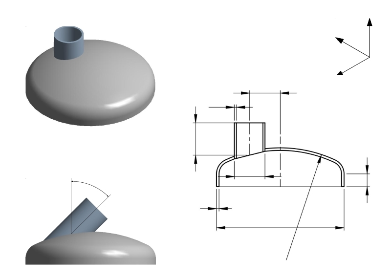
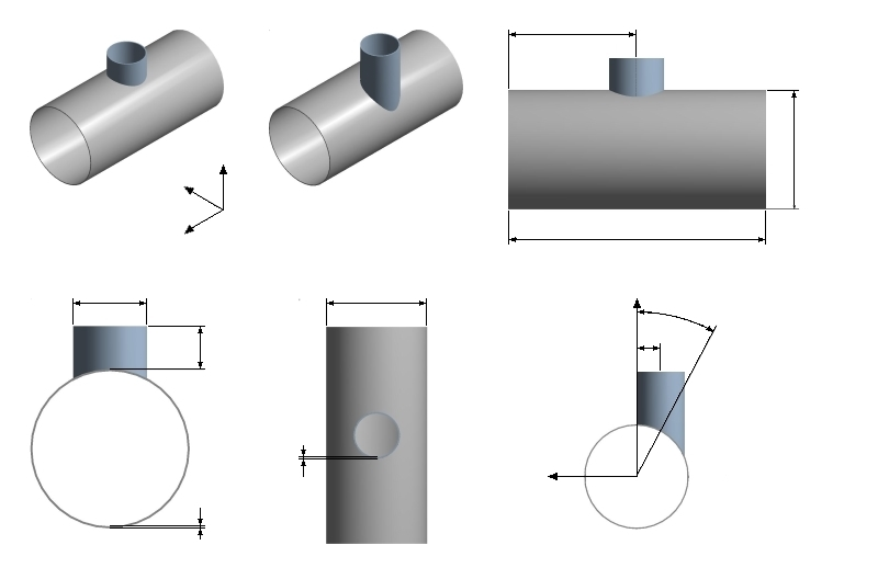
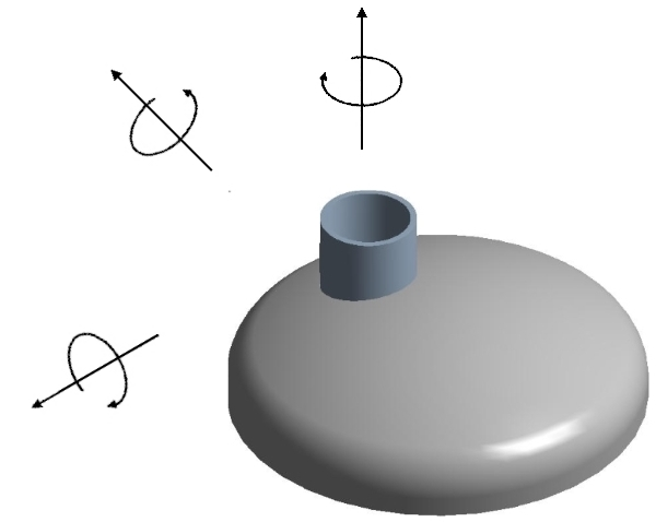
Calculation workflow
- Define the model: The geometry of the main body and nozzle is taken over; the switches "longitudinal stress in shell considered", "longitudinal stress in nozzle considered" and "rigid nozzle end (flange)" define the mechanical substitute model.
- Apply the loads: Internal pressure as well as external forces and moments are applied; the parameter "loads apply at" defines the point on the nozzle where the external loads are introduced – this significantly affects the bending moments at the penetration.
- Create and solve the FE model: The module generates the mesh ("creating FE model") and solves the model ("calculation"). Via the sequence control, the calculation can be paused, only the model created, or the analysis run straight through.
- Evaluate the stresses: The stress evaluation follows the selected assessment concept; with element evaluation according to ASME VIII-2 activated, the stresses are categorized into primary membrane, bending and secondary components and compared with the allowable values.
- Report the utilization: As the summarizing result, the utilization is output – the ratio of the assessed stress to the allowable value. Values up to 100% count as verified.
Input quantities
| Quantity | Symbol | Unit |
|---|---|---|
| Design temperature | Temp | °C |
| Material | Grundkörper | – |
| Material | Stutzen | – |
| Material | Verstärkung | – |
| Outside diameter | d1 | mm |
| Outside diameter | Da | mm |
| Wall thickness | s1 | mm |
| Wall thickness | sa | mm |
| Length | h | mm |
| Height of skirt | l | mm |
| Diameter | dv | mm |
| Thickness of reinforcing plate | sv | mm |
| Diameter of crown | Dk | mm |
| Nozzle offset in Y-direction | x1 | mm |
| Angle of inclination around Z | x2 | ° |
| Direct. of inclination XY plane | x3 | ° |
| Distance of calculation circles | Δ | mm |
| Number of calculation circles around nozzle | n1 | - |
| Number of nodes on calculation circles | n2 | - |
| Set-in nozzle Y/N | Stutzen | mm |
| Combined stress | Sm | N/mm² |
| Combined stress | Sm | N/mm² |
| Combined stress | Sm | N/mm² |
| Modulus of elasticity | E | N/mm² |
Calculated results
| Quantity | Symbol | Unit |
|---|---|---|
| Utilization | U | – |
| Ergebnisses | Ergebnisses | – |
| Richtung | X = Y = Z = | mm |
| Richtung | X = Y = Z = | mm |
| Richtung | X = Y = Z = | mm |
| Achse | X = Y = Z = | ° |
| Achse | X = Y = Z = | ° |
| Achse | X = Y = Z = | ° |
Calculation options
Language
German · English
Outside diameter
Detailed · Short
Stress evaluation according to
65 · 68 · 69
Creating FE model
Automatically · Always · Manually
Calculation
Automatically · Always · Manually
Frequently asked questions
Why is element evaluation according to ASME VIII-2 recommended?
ASME VIII Division 2 Part 5 defines an established, clearly documented procedure for evaluating FE stresses (stress categorization or elastic stress analysis with linearization). It ensures that local peak stresses are not incorrectly treated as primary stresses, and the verification is transparent for notified bodies and inspectors.
What does the option "rigid nozzle end (flange)" mean?
A flange welded to the nozzle end stiffens the nozzle cross section against ovalization. If the option is activated, the nozzle end remains plane and circular in the model, which changes the local flexibility of the penetration and thus the calculated stresses. If there is no flange near the nozzle, the option should remain deactivated.
What role does the point of application of the external loads play?
Forces transverse to the nozzle axis generate a bending moment at the penetration that is proportional to the lever arm between the load application point and the shell. If the loads are applied at the nozzle end instead of at the penetration, the moments increase accordingly – a common mistake is adopting piping loads without checking the reference point.
Does the module replace the opening reinforcement calculation to AD 2000 B 9 or EN 13445?
No, it complements it. The area-replacement methods cover the pressure verification of openings; the FEM analysis is intended for external nozzle loads and for cases outside the limits of applicability of the formula methods. For standard cases, design by formula remains the faster and sufficient route.