Engineering task and calculation objective
Module EN13.05 calculates fixed tubesheets of heat exchangers to DIN EN 13445-3, clause 13.5. In a fixed-tubesheet exchanger, both tubesheets are welded rigidly to the shell; tubes and shell form a statically indeterminate system in which pressure and temperature loads interact. The tubesheet calculation is therefore inseparable from the verification of the axial tube and shell loading.
To calculate a fixed tubesheet to EN 13445-3 means treating the tubesheet as a perforated plate resting on the elastic foundation of the tube field and verifying it for all governing load cases: shell-side and tube-side pressure acting individually and together, each with and without the thermal expansion difference between tubes and shell — the standard defines the typical seven load cases for this, supplemented by start-up/shutdown states and exceptional operating conditions. An expansion bellows in the shell reduces the restraint forces and enters the calculation with its spring rate.
The module delivers the verifications for the tubesheet, the tubes (including buckling of the tubes in compression), the shell and the tube-to-tubesheet joint, and is used for the design and re-rating of fixed-tubesheet heat exchangers in process and power plants.
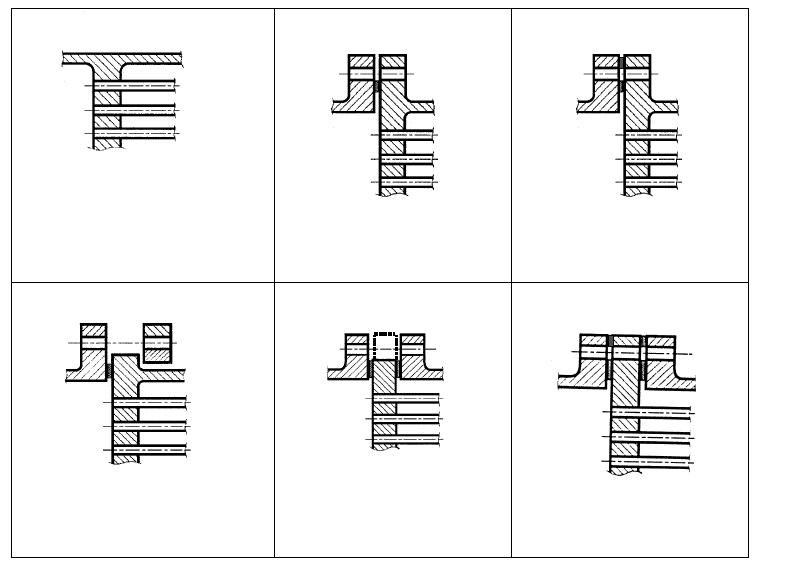
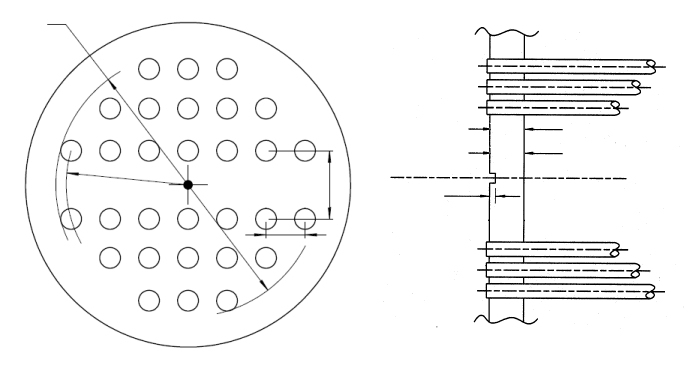
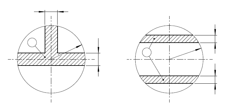
Standard and calculation basis: DIN EN 13445-3/13.5: 2021-12
Calculation workflow
- Define configuration and geometry: The attachment configuration of the tubesheet (integral, gasketed, with flange), the tube-field geometry, the tube dimensions and the shell and channel data are entered; an existing expansion bellows is accounted for with its stiffness.
- Set up the load cases: The shell-side and tube-side design pressures, the test pressures and the thermal expansion difference between tubes and shell are combined into the governing load cases — including start-up and shutdown states as well as exceptional operating conditions.
- Calculate the system stiffnesses: From the axial stiffness of the tube field, the shell and, where applicable, bellows stiffness, and the bending stiffness of the perforated tubesheet, the coupling quantities of the statically indeterminate system are formed.
- Determine loadings for each load case: For each load case, the bending stresses in the tubesheet, the axial stresses in tubes and shell and the forces on the tube-to-tubesheet joint are calculated; for tubes in compression, buckling resistance is verified in addition.
- Combine the verifications: All component verifications must be satisfied in every load case; the module reports the utilizations and shows which load case governs the tubesheet thickness, the tubes or the shell.
Input quantities
| Quantity | Symbol | Unit |
|---|---|---|
| Configuration of the tubesheet | Rohrboden | – |
| Calculation acc. 13.5.9 (reinforced shell) | Schale) | – |
| Design pressure (shell-side) | Ps,Op | MPa(p) |
| Design pressure (tube-side) | Pt,Op | MPa(p) |
| Test pressure (shell-side) | Ps,Test | MPa(p) |
| Test pressure (tube-side) | Pt,Test | MPa(p) |
| Load case 1 | Ps = 0, Pt, γ=0 OC1 | – |
| Load case 2 | Ps, Pt = 0, γ=0 OC2 | – |
| Load case 3 | Ps, Pt, γ=0 OC3 | – |
| Load case 4 | Ps = 0, Pt = 0, γ OC4 | – |
| Load case 5 | Ps = 0, Pt, γ OC5 | – |
| Load case 6 | Ps, Pt = 0, γ OC6 | – |
| Load case 7 | Ps, Pt, γ OC7 | – |
| Load case 1 | Ps = 0, Pt, γ=0 TC1 | – |
| Load case 2 | Ps, Pt = 0, γ=0 TC2 | – |
| Load case 3 | Ps, Pt, γ=0 TC3 | – |
| Start-up and Shut-down | SSC | – |
| Exceptional operating conditions | EXC | – |
| Material | Boden | – |
| Rohre | Rohre | – |
| Schale | Schale | – |
| Vorkammer | Vorkammer | – |
| Rohrboden | Rohrboden | – |
| Design temperature | T | °C |
Calculated results
| Quantity | Symbol | Unit |
|---|---|---|
| Minimum length l1 observed? | Check_l1 | – |
| Minimum length l'1 observed? | Check_l'1 | – |
| Is μ* in a valid range? | Check_\u03bc* | – |
| OC1 | OC1 | – |
| OC2 | OC2 | – |
| OC3 | OC3 | – |
| OC4 | OC4 | – |
| OC5 | OC5 | – |
| OC6 | OC6 | – |
| OC7 | OC7 | – |
| TC1 | TC1 | – |
| TC2 | TC2 | – |
| TC3 | TC3 | – |
| SSC | SSC | – |
| EXC | EXC | – |
| OC1 | OC1 | – |
| OC2 | OC2 | – |
| OC3 | OC3 | – |
| OC4 | OC4 | – |
| OC5 | OC5 | – |
| OC6 | OC6 | – |
| OC7 | OC7 | – |
| TC1 | TC1 | – |
| TC2 | TC2 | – |
Calculation options
Configuration of the tubesheet
a - tubesheet integral with shell and channel · b - tubesheet integral with shell and gasketed with channel, extended as a flange · b' - tubesheet integral with shell and gasketed with channel, extended as a flange, full-face gasket · c - tubesheet integral with shell and gasketed with channel, not extended as a flange · d - tubesheet gasketed with shell and channel, not extended as a flange · d' - tubesheet gasketed with shell and channel, not extended as a flange, full-face gasket
Calculation acc. 13.5.9 (reinforced shell)
No · Yes
Tube arrangement
triangular · rectangular
Tube - Tubesheet connection
welded · rolled in without groove acc. fig. 13.7.3-3 · rolled in with one groove · rolled in with two grooves · welded acc. fig. 13.12.3-1 · welded acc. fig. 13.12.4-1 to 13.12.7-1
Determination of buckling length of tubes
calculate · enter
Type of tube support by baffles
1 baffle and not all tubes supported per one baffle or no baffle · 1 or multiple baffles and all tubes supported per one baffle · multiple baffles and not all tubes supported per one baffle
Is there a bellows in the shell?
No · Yes
Determination of bolt load
calculate · enter
Frequently asked questions
Why are the temperature load cases often governing for a fixed-tubesheet exchanger?
Because tubes and shell are rigidly coupled, every temperature difference between them creates a restraint: if the tubes expand more than the shell, they are put into compression (buckling risk) and the tubesheet into bending. These restraint forces can significantly exceed the pure pressure loads — which is why the standard requires the load cases with and without the thermal expansion difference.
When is an expansion bellows in the shell required?
When the restraint forces from the expansion difference would lead to inadmissible stresses in tubes, shell or tubesheet without a bellows — typically for large temperature differences between the tube side and the shell side, or for materials with different coefficients of thermal expansion. The bellows lowers the axial system stiffness of the shell and thus the restraint forces; its spring rate enters the calculation per 13.5 directly.
What distinguishes the seven load cases of the standard?
They systematically combine: tube-side pressure only, shell-side pressure only, both pressures together — each without and with the thermal expansion difference — plus the pure temperature load case. Since the sign of the axial tube force changes with the combination, each of these cases can govern a different component (tubesheet, tube buckling, tube-to-tubesheet joint); none may be omitted.
Why must buckling of the tubes be verified?
In load cases with tubes in compression, the tubes act as slender struts that can buckle between the baffles. The allowable compressive stress is therefore limited via the buckling length between the support points. Too large a baffle spacing reduces the allowable tube compressive force and can determine the entire design.