Engineering task and calculation objective
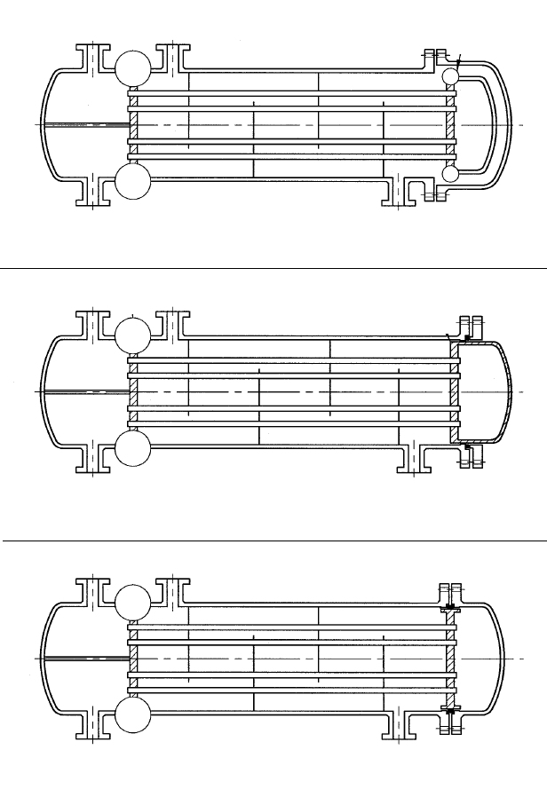
The EN13.06 module calculates the tubesheets of floating-head heat exchangers to DIN EN 13445-3, Clause 13.6. In the floating-head design, only one of the two tubesheets is rigidly connected to the shell and channel; the second tubesheet can move axially together with the tube bundle. Differential thermal expansion between tube bundle and shell is therefore accommodated largely without restraint forces – a decisive advantage where large temperature differences exist between the shell side and the tube side.
To calculate a floating-head heat exchanger, both tubesheets (stationary and floating) must be verified for all governing combinations of shell-side and tube-side design pressure, including the test conditions. The module therefore requests the design pressures and test pressures of both sides separately and examines the resulting load cases. It is equally suited to designing new process equipment and to re-rating existing shell-and-tube heat exchangers to the European code.
The calculation follows the harmonized pressure vessel standard DIN EN 13445-3 and can therefore be applied directly to pressure equipment within the scope of the Pressure Equipment Directive (2014/68/EU).
Standard and calculation basis: DIN EN 13445-3/13.6: 2021-12
Calculation workflow
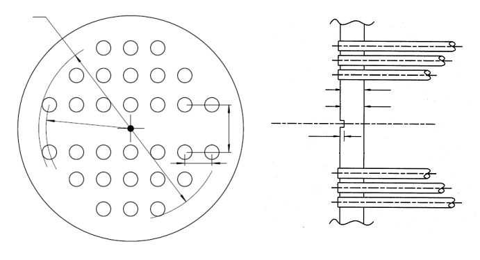
- Define configuration and geometry: First, the floating-head configuration per Clause 13.6 is selected (e.g. internal floating head or externally sealed floating head) and the geometry is entered: tubesheet diameter, tube field, tube pitch, tube dimensions, and the connection details to shell, channel, and flanges.
- Determine the effective properties of the tubesheet: From the tube pitch and hole diameter, the effective characteristics of the perforated plate are determined, in particular the ligament efficiency and the effective bending stiffness. They describe how much the drilled field reduces the load-bearing capacity of the plate compared with an unperforated plate.
- Set up the load cases from the pressure combinations: Using the shell-side and tube-side design pressures together with the associated test pressures, all governing load cases are formed: each side acting alone, both sides acting together, and the test conditions. Since the shell side and tube side can be depressurized independently, every combination must be verified.
- Perform the stress checks for both tubesheets: For the stationary and the floating tubesheet, the bending stresses and shear stresses are calculated according to the equations of Clause 13.6 and compared with the allowable values derived from the nominal design stress and the load case category.
- Verify the tubes and adjacent components: In addition, the axial tube stresses, the tube-to-tubesheet joint and, for tubes in compression, the stability check against buckling are examined. The transitions to shell and channel as well as the associated flanged joints are covered by the subsequent conditions.
Input quantities
| Quantity | Symbol | Unit |
|---|---|---|
| Type of floating head exchanger | Bauart | – |
| Configuration of fixed tubesheet | Rohrboden | – |
| Configuration of floating tubesheet | Rohrboden | – |
| Shell-side design pressure (inside) | PBs | MPa(p) |
| Tube-side design pressure (inside) | PBt | MPa(p) |
| Shell-side test pressure (inside) | PPs | MPa(p) |
| Tube-side test pressure (inside) | PPt | MPa(p) |
| Load case (1) | Ps=0 Pt OC1 | – |
| Load case (2) | Ps Pt=0 OC2 | – |
| Load case (3) | Ps Pt OC3 | – |
| Load case (1) | Ps=0 Pt TC1 | – |
| Load case (2) | Ps Pt=0 TC2 | – |
| Load case (3) | Ps Pt TC3 | – |
| Start-up and Shut-down | SSC | – |
| Exceptional operating conditions | EXC | – |
| Material | Boden | – |
| Rohre | Rohre | – |
| Schale | Schale | – |
| Vorkammer | Vorkammer | – |
| Design temperature | T | °C |
| Nominal wall thickness *) | eN | mm |
| Outside diameter | A | mm |
| Poisson's ratio | \u03bd | - |
| Tolerance | \u03b4 | mm |
Calculated results
| Quantity | Symbol | Unit |
|---|---|---|
| Ratio of effective tubesheet diameters | Check_De,f_De | – |
| Is µ within the allowable range? | Check_\u00b5* | – |
| Allowable distance of tube rows | Check_Ul_p | – |
| Minimum required tube sheet thickness acc. to 13.6.2.1e | ea | mm |
| Ratio tubesheet diameter - tube sheet thickness | Check_e_dt | – |
| Ratio inside diameter of channel and of shell | Check_Ds_Dc | – |
| Unperforated diametral rows permitted? | Check_Do_De | – |
| Minimum length of shell from tubesheet on | Ls,min | mm |
| Minimum length of channel from tubesheet on | Lc,min | mm |
| OC1 | OC1 | – |
| OC2 | OC2 | – |
| OC3 | OC3 | – |
| TC1 | TC1 | – |
| TC2 | TC2 | – |
| TC3 | TC3 | – |
| SSC | SSC | – |
| EXC | EXC | – |
| OC1 | OC1 | – |
| OC2 | OC2 | – |
| OC3 | OC3 | – |
| TC1 | TC1 | – |
| TC2 | TC2 | – |
| TC3 | TC3 | – |
| SSC | SSC | – |
Calculation options
Type of floating head exchanger
1 - Immersed floating head - Fig. 13.6.1-1 (a) · 2 - Externally sealed floating head - Fig. 13.6.1-1 (b) · 3 - Internally sealed floating head - Fig. 13.6.1-1 (c)
Configuration of fixed tubesheet
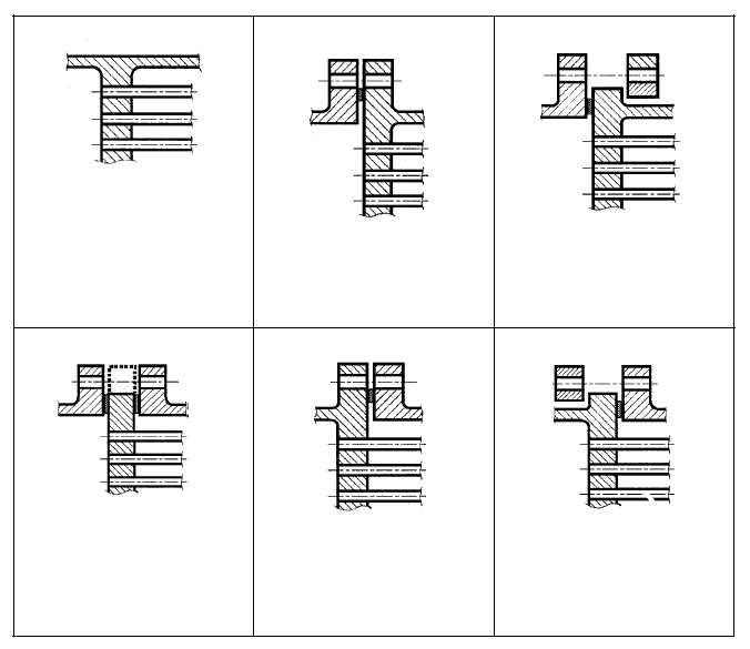
A - Tubesheet integral with shell and channel · b - tubesheet extended as flange / integral with shell / gasketed with channel / narrow-face gasket · b' - tubesheet extended as flange / integral with shell / gasketed with channel / full-face gasket · c - tubesheet integral with shell and gasketed with channel, not extended as a flange · d' - tubesheet gasketed with shell and channel, not extended as a flange, full face gasket · d - tubesheet gasketed with shell and channel, not extended as a flange · e - tubesheet extended as flange / gasketed with shell / integral with channel / narrow-face gasket · e' - tubesheet extended as flange / gasketed with shell / integral with channel / full-face gasket · f - tubesheet not extended as flange / gasketed with shell / integral with channel
Configuration of floating tubesheet
A - Tubesheet integral · B - Tubesheet gasketed, extended as a flange · C - Tubesheet gasketed, not extended as a flange
Tube arrangement
triangular · rectangular
Tube - Tubesheet connection
welded · rolled in without grooves acc. fig. 13.7.3-3 · rolled in with one groove · rolled in with two grooves · welded acc. fig. 13.12.3-1 · welded acc. fig. 13.12.4-1 to 13.12.7-1
Determination of buckling length of tubes
calculate · enter
Type of tube support by baffles
1 baffle and not all tubes supported per one baffle or no baffle - Fig.13.9.3-1 (a) · 1 or multiple baffles and all tubes supported per one baffle - Fig. 13.9.3-1 (c) · multiple baffles and not all tubes supported per one baffle - Fig. 13.9.3-1 (b)
Determination of bolt load
calculate · enter
Frequently asked questions
How does a floating tubesheet differ from a fixed tubesheet per Clause 13.5?
In a fixed-tubesheet heat exchanger (Clause 13.5) both tubesheets are rigidly connected to the shell; temperature differences between tubes and shell then generate restraint forces that enter the calculation. With a floating head, one tubesheet can move axially, so these additional thermal loads are largely eliminated. The calculation to 13.6 therefore concentrates on the pressure combinations of shell side and tube side.
Why must the test pressures of both sides be entered separately?
During the pressure test each side is usually pressurized individually while the other side is unpressurized. This single-sided condition is often the governing load case for the tubesheet, because the pressure difference across the plate reaches its maximum. The standard therefore requires verification of all combinations, including the test conditions with the allowable stresses of the test case.
What role does the ligament efficiency play in the tubesheet calculation?
The ligament efficiency describes the weakening of the plate by the drilled field: the tighter the tube pitch relative to the hole diameter, the smaller the remaining load-bearing ligament width and the higher the actual stresses in the tubesheet. It enters directly into the effective properties of the perforated plate and has a decisive influence on the required tubesheet thickness.
Does the calculation also cover the flanges and gaskets of the floating head?
Clause 13.6 covers the tubesheet with its boundary conditions from shell, channel, and, where applicable, an integral or bolted flange. The complete flanged joint with gasket and bolting is verified in separate modules to DIN EN 13445-3 Clause 11 (or EN 1591-1); the subsequent conditions in the module establish the link.