Engineering task and calculation objective
The ENAJ module calculates tubesheets of shell-and-tube heat exchangers using the alternative method of DIN EN 13445-3 Annex J. While the standard methods of clause 13 are tailored to symmetrical standard configurations, Annex J permits the calculation of non-symmetrical units in which tubesheet 1 and tubesheet 2 differ in thickness, material or edge condition, as well as tubesheets with untubed areas whose size exceeds the limits of clause 13, for instance around access lances, deflection zones or special bundle geometries.
The method treats the tubesheet as a plate on an elastic foundation: the tube bundle acts as a spring support whose stiffness follows from the tube geometry, tube count and tube material, while the shell, channels, connected flanges and, where present, an expansion joint provide the boundary conditions. Fixed tubesheets, floating tubesheets and U-tube designs are covered, as are the differential thermal expansion between shell and tubes, additional axial loads and dead weight.
As results, the module delivers the load ratios for bending, shear, untubed areas, additional dead weight and combined loadings, together with the check of the associated conditions of the standard (e.g. J.9.1-4 to J.9.5-1). In addition, the tubes themselves are verified: allowable longitudinal stresses in tension and compression including buckling resistance, and the load-bearing capacity of the tube-to-tubesheet connection.
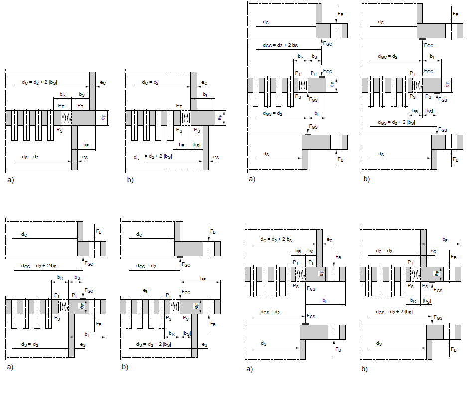
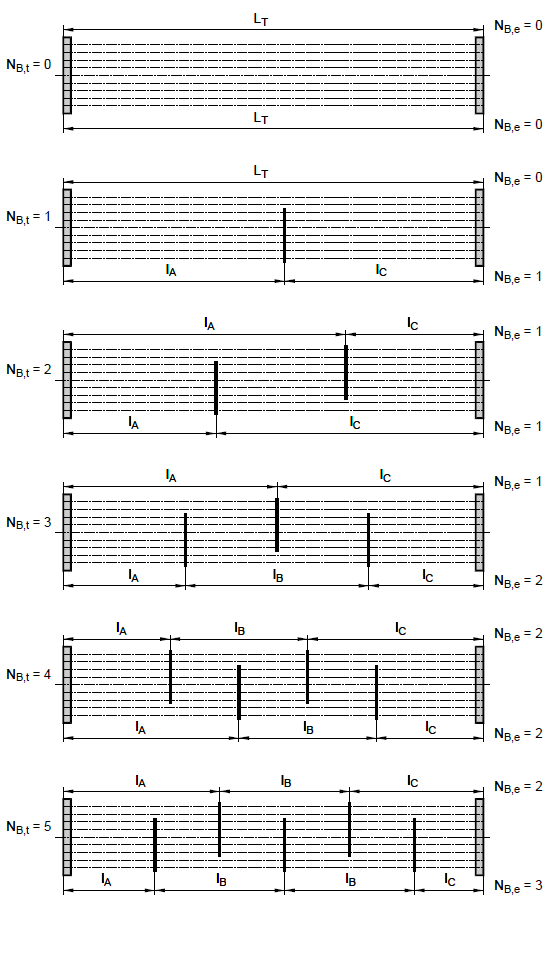
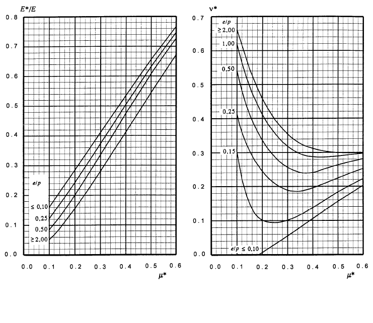
Standard and calculation basis: DIN EN 13445-3: 2021-12 Anhang J
Calculation workflow
- Define the design type and geometry: First, the heat exchanger type is selected: fixed tubesheet, floating tubesheet or U-tube bundle, with or without an expansion joint in the shell. The two tubesheets are described separately, since Annex J expressly permits different thicknesses, materials and edge conditions on each side; untubed areas are recorded by location and size.
- Determine stiffnesses and boundary conditions: The foundation stiffness of the bundle follows from the number of tubes, tube dimensions and pitch; the rotational spring at the plate edge follows from the shell, channel and flange connections. These elastic couplings determine how pressure and temperature loads are shared between tubesheet, tubes and shell.
- Set up the load cases: The loadings are calculated for all governing combinations of tube-side and shell-side pressure, temperature difference between tubes and shell, and additional axial and dead weight loads. Start-up, test and upset conditions (subsequent conditions) can also govern the design.
- Verify the tubesheet: For each load case, the bending and shear loading of the tubed region and the stresses in untubed areas are determined and checked as load ratios against the conditions of clause J.9, including the additional checks for dead weight and combined loadings.
- Verify the tubes and the tube-to-tubesheet connection: The longitudinal stresses of the tubes are checked against the allowable values in tension (condition J.7.3-1) and compression (condition J.7.3-2, with a buckling check for slender tubes). It is additionally verified that the tube-to-tubesheet connection, whether welded or expanded, transfers the maximum tube force at the allowable design stress.
Input quantities
| Quantity | Symbol | Unit |
|---|---|---|
| Tubesheet type acc. fig. | -J13 | – |
| Tube bundle orientation | J.9.4 | – |
| Tube ends | J.7.3.2 | – |
| Cross-sectional area of the tubed region | J.7.5-7 AR | mm² |
| Minimum area of the tubed region | J.5.1.1.3.2 AR(min) | mm² |
| Determinant of all compliances | J.10.3-13 B0 | – |
| Compliances for the tube bundle | J.10.3-7 BR1 | – |
| Compliances for the tube bundle | J.10.3-8 BR2 | – |
| Compliances for the tube bundle | J.10.3-9 BR3 | – |
| Compliances for shell and channel | J.10.3-10 BS1 | – |
| Compliances for shell and channel | J.10.3-11 BS2 | – |
| Compliances for shell and channel | J.10.3-12 BS3 | – |
| True width of a flange like part of the tubesheet Figure J-10 -J-13 | bF | mm |
| Maximum width of the untubed rim Figure J-7 | bU | mm |
| Factor for the fatigue design Figure J-15 | C1 | – |
| Factor for the fatigue design Figure J-15 | C2 | – |
| Inside diameter of the channel Figure J-10 -J-13 | dC | mm |
| Inside diameter of shell Figure J-10 -J-13 | dS | mm |
| Tubehole diameter, real value | d0 | mm |
| Tube pitch in the tubed region Figure J-7 | p | mm |
| Tube outside diameter | dT | mm |
| Radius of the outermost tube hole centre Figure J-7(a) | r0 | mm |
| Maximum value of d1 | J.5.1.1.2 d1(max) | mm |
| Minimum value of d1 | J.5.1.1.3 d1(min) | mm |
Calculation options
Tubesheet type acc. fig.
Show overview graphics · 10 · 11 · 12 · 13
Tube bundle orientation
vertical · horizontal
Tube ends
welded · expanded · expanded and welded
Tube pitch type
triangular · rectangular · undefined
Buckling length of tubes, internally sealed floating head, J.7.1.3
Twisting prevented · Twisting not prevented
Type
U-tube heat exchanger · Heat exchanger with immersed floating head · Heat exchanger with externally sealed floating head · Heat exchanger with internally sealed floating head · Fixed tubesheets with expansion bellows · Fixed tubesheets without expansion bellows
Frequently asked questions
When do I need Annex J instead of the tubesheet calculation to clause 13?
Clause 13 largely assumes symmetrical units with identical tubesheets and limited untubed zones. Annex J is the tool of choice when the two tubesheets are of different design, when large untubed areas exceed the limits of clause 13, or when the interaction of tubesheet, bundle, shell, flanges and expansion joint is to be captured more accurately. Both methods comply with the standard; Annex J is more general but demands more input data.
Why is the temperature difference between tubes and shell so critical for fixed tubesheet exchangers?
With rigidly welded-in tubesheets, shell and tubes form a statically indeterminate system: if the tubes expand more than the shell (or vice versa), axial restraint forces arise that bend the tubesheets, load the tubes in compression up to buckling, and stress the tube-to-tubesheet connections. An expansion joint in the shell relieves these restraint forces. The load cases with maximum temperature difference, often start-up and shutdown, therefore regularly govern the design.
What do the module's load ratios tell me?
Each load ratio is the ratio of existing to allowable loading for a particular check: bending of the tubesheet, shear at the bundle edge, untubed areas, additional dead weight and combined loadings. Values up to 1.0 mean the associated condition of the standard is satisfied. The breakdown also shows which mechanism limits the design and where a change of thickness, material or design type would be most effective.
Why is the compressive stress of the tubes limited separately?
Tubes are slender members: under axial compression they fail not by reaching the yield strength but by buckling. The allowable compressive stress according to condition J.7.3-2 therefore depends on the buckling length between supports, with baffles acting as lateral supports. Wide baffle spacings or missing support plates in edge zones reduce the allowable compressive stress considerably.