Engineering task and calculation objective
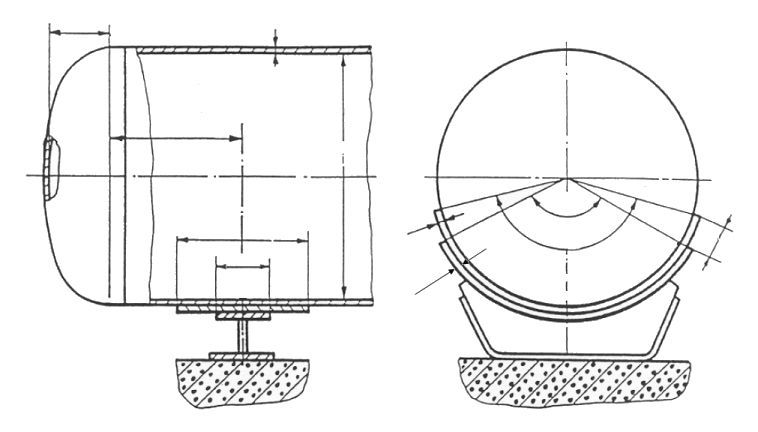
This module calculates horizontal cylindrical vessels on saddle supports to DIN EN 13445-3 clause 16.8. It covers vessels without a reinforcement ring on two or more saddles — the standard design for horizontal storage tanks, heat exchangers, and process vessels in plant engineering. The vessel acts as a beam on several supports: self-weight and contents generate global bending moments and shear forces, while the saddles additionally introduce local stresses into the shell.
The standard carries out the verifications separately for the governing locations: between the saddles, the longitudinal stresses from the global bending moment are limited (clause 16.8.6); at the saddle, the combined global and local loads on the shell are verified (16.8.7); and in addition, the load-bearing capacity at the saddle horn and the saddle plate is checked (16.8.8). For thin-walled vessels, stability against buckling under longitudinal compressive stresses must also be considered.
Anyone who wants to calculate a horizontal vessel on saddle supports obtains with this module the complete code-compliant verification to DIN EN 13445-3 — including the influence of saddle position, saddle angle, and, where applicable, a reinforcing plate underneath on the local stresses.
Standard and calculation basis: DIN EN 13445-3/16.8: 2018-12
Calculation workflow
- Enter vessel and saddle geometry: The diameter, wall thickness, and length of the cylindrical shell including the heads are entered, plus the number and position of the saddles (distance from the vessel end), the saddle contact angle, and the width of the saddle plate and of any reinforcing plate.
- Determine the loads: Governing is the weight of the vessel with its contents — usually the water fill level during the pressure test as the most unfavorable case — superimposed where applicable with internal or external pressure and additional loads.
- Determine the internal forces as a beam: The vessel is treated as a beam on the saddle supports; from this follow the global bending moments at mid-span and above the saddles as well as the shear forces at the supports.
- Carry out the verification between the saddles: Per clause 16.8.6, the longitudinal stresses from bending moment and pressure in the shell between the saddles are verified against the allowable stress and against the buckling limit for longitudinal compression.
- Carry out the verification at the saddle: Per clauses 16.8.7 and 16.8.8, the local loads at the support are checked: combined longitudinal and circumferential stresses at the governing points of the saddle horn and in the support region, including the effect of a reinforcing plate.
- Adjust the design: If limits are exceeded, a larger saddle angle, a wider or thicker reinforcing plate, a saddle position closer to the heads, or a greater wall thickness will help; the verification is then repeated.
Input quantities
| Quantity | Symbol | Unit |
|---|---|---|
| Analysis thickness | ea | mm |
| Vessel inside diameter | Di | mm |
| Distance from horn of saddle to end of reinforcing plate | a2 | mm |
| Reinforcement plate thickness | e2 | mm |
| Saddle support plate thicknes without allowances | e1 | mm |
| Length of cylindrical part of vessel (including cylindrical part of heads) | L | mm |
| Max. cylinder length | Lmax | mm |
| Distance from saddle support to adjacent end of cylindrical part | a1 | mm |
| Axial width of saddle support | b1 | mm |
| Width of the reinforcing plate | b2 | mm |
| Final wall thickness | en | mm |
| Joint coefficient | z | - |
| Density of filling medium | Rf | kg/m³ |
| Effective combined wall thickness | ec | mm |
| Allowable design stress at load case | f2 | N/mm² |
| Design temperature | T | °C |
| Material | Werkstoffnummer | – |
| Design strength | K | N/mm² |
| Design strength (Test) | Ktest | N/mm² |
| Safety factor | S | - |
| Safety factor (Test) | Stest | - |
| Wall thickness allowance | C1 | mm |
| Corrosion allowance | C2 | mm |
| Design stress | f | N/mm² |
Calculated results
| Quantity | Symbol | Unit |
|---|---|---|
| K11 | K11 | - |
| Moment at saddle 1 and 2 | M1,2 | N·mm |
| Proof of saddle support is furnished. | S32 | – |
| Moment at saddles i=1 und i=n | Mn | N·mm |
| Moment between saddle 1 and 2 | M12 | N·mm |
| Allowable saddle load acc. eq. 15; S3/2 | F4 zul | N |
| Influence factor for saddle width 16.8.8 a) | β | - |
| Allowable saddle load acc. eq. 16; S3/2 | F5 zul | N |
| K3 | K3 | - |
| K4 | K4 | - |
| K5 | K5 | - |
| K6 | K6 | - |
| K7 | K7 | - |
| K8 | K8 | - |
| K9 | K9 | - |
| K10 | K10 | - |
| Pos.2 | ϑ1 | - |
| Pos.3 | ϑ1 | - |
| P2 | ϑ2,1 | - |
| P3 | ϑ2,1 | - |
| P2 | ϑ2,2 | - |
| P3 | ϑ2,2 | - |
| Pos.2 | K1 | - |
| L2 | K1 | - |
Calculation options
Proof of saddle support
No proof · 1
Type
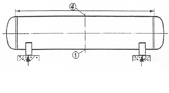
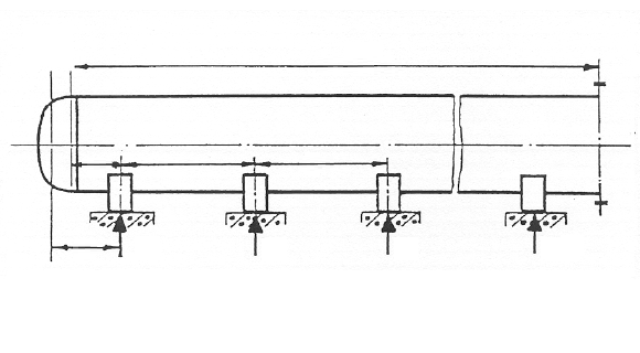
Type A - Vessel symmetrically on two saddles · Type B – Vessel symmetrically on three or more equidistant saddles
Reinforcing plate
Yes · No
Frequently asked questions
Why should the saddles be placed as close to the heads as possible?
The dished heads locally stiffen the cylindrical shell. If the saddle stands within the stiffening influence of the head, the local circumferential bending stresses at the saddle horn are significantly reduced. At the same time, too large a saddle spacing increases the mid-span moment between the saddles — the saddle position is therefore always a compromise, which the verification quantifies.
Which load case is typically governing?
Usually the hydrostatic pressure test with complete water filling, because the fill weight is then greatest — even for vessels that only contain gas or light media in service. In addition, the vacuum case can become critical, since external pressure and saddle-induced longitudinal compressive stresses jointly challenge the buckling safety.
When is a reinforcing plate under the saddle required?
When the local stresses at the saddle horn exceed the allowable values but the wall thickness is not to be increased. The reinforcing plate is effective only if it extends sufficiently far beyond the saddle horn and is welded to the shell; its creditable effect is regulated in the standard. Alternatively, a larger contact angle helps (120° is common).
Does the module also cover vessels with reinforcement rings?
No, the module covers vessels without a reinforcement ring per clause 16.8. Ring-stiffened horizontal vessels, in which the saddle forces are distributed via rings, are a separate application with a different calculation procedure.