Engineering task and calculation objective
During transport and erection of pressure vessels, considerable loads are introduced directly into the vessel shell via lifting lugs. This module calculates lifting lugs on pressure vessels to DIN EN 13445-3, clause 16.7 — in longitudinal or circumferential orientation, each with or without a reinforcing plate. The strength verification of the lug itself and of the weld is carried out additionally to the German strength guideline catalogue RKF (Richtlinienkatalog Festigkeit), sheet BR A 62.
The critical point is rarely the lug itself: what usually governs are the local membrane and bending stresses that the eccentrically applied lifting load generates in the thin-walled vessel shell. The code limits these local loadings as a function of shell geometry, load direction and lug arrangement; a reinforcing plate enlarges the load introduction area and reduces the shell loading.
The verification is needed for every vessel design that is lifted, turned or upended after shop assembly — from small apparatus to columns. If you want to calculate lifting lugs to EN 13445, this module verifies shell, reinforcing plate, lug and weld in a single pass.
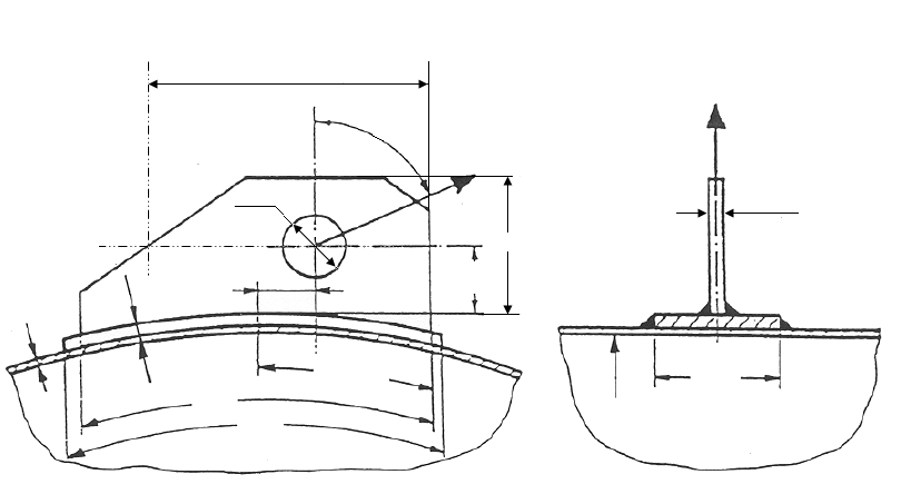
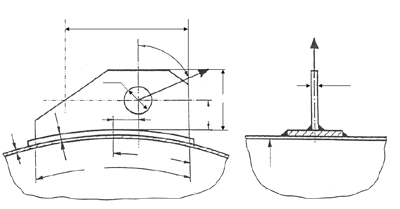
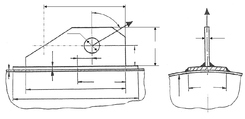
Standard and calculation basis: DIN EN 13445-3/16.7: 2018-12
Calculation workflow
- Select design type and arrangement: The orientation of the lug (longitudinal to the vessel axis or circumferential), the lug geometry and whether a reinforcing plate is provided are specified. For the reinforcing plate, width, length, thickness and material are entered.
- Determine the loads from the lifting operation: The lifting load acting on the lug is applied, including load direction (sling angle) and dynamic amplification during lifting. For multi-leg rigging, the most unfavourable load distribution among the individual lugs must be considered; the verifications are carried out separately with the properties and safety factors of the test and operating conditions.
- Verify the local shell loading: From lifting load and lever arm, the force and moment at the welded attachment are obtained. The module determines the local stresses in the vessel shell according to the rules for local load introductions of clause 16 and compares them with the allowable stress — with a reinforcing plate, using the enlarged effective area.
- Verify lug and weld to RKF: The strength verification of the lug (cross-section at the lug eye, bearing pressure) and of the connecting weld is performed to RKF BR A 62. This covers not only the shell but also the rigging interface and the connection completely.
- Assess the result and adjust the design: The module reports the utilization ratios of all verification points. If limits are exceeded, a reinforcing plate can be added or enlarged, the lug relocated, or the rigging configuration (sling angle, spreader beams) changed, and the verification repeated immediately.
Input quantities
| Quantity | Symbol | Unit |
|---|---|---|
| Design temperature | Temp | °C |
| Material of shell | Schale | - |
| Material of lug | Hebeöse | - |
| Eccentricity of load | a1 | mm |
| Distance from load to shell | a2 | mm |
| Height of lug | h | mm |
| Thickness of lug | sl | mm |
| Length of lug | b1 | mm |
| Angle between the resulting lifting force and the normal to the shell wall | β | ° |
| Manufacturing allowance for shell | c1S | mm |
| Corrosion allowance for shell | c2S | mm |
| Nominal wall thickness of shell | en | mm |
| Outside diameter of shell | De | mm |
| Total vessel weight | W | N |
| Local force at the shell | FR | N |
| Design pressure | P | MPa(p) |
| Allowable design stress | f | N/mm² |
| Coefficient | K2 | - |
| Maximum allowable local force at shell | FR = ≤ FR,max = | N |
| Strength Testing Operation | KL' KL | N/mm² |
| Safety Testing Operation | SL' SL | - |
| Design case | (Betrieb/Prüfung) | – |
| Type of shell | Bauform | - |
| _Bedingung | FR = ≤ FR,max = | - |
Calculated results
| Quantity | Symbol | Unit |
|---|---|---|
| Design temperature | Temp | °C |
| Material of shell | Schale | - |
| Material of reinforcing plate | Verstärkung | - |
| Material of lug | Hebeöse | - |
| Eccentricity of load | a1 | mm |
| Distance from load to shell | a2 | mm |
| Height of lug | h | mm |
| Thickness of lug | sl | mm |
| Length of lug | b1 | mm |
| Width of reinforcing plate | b2 | mm |
| Length of reinforcing plate | b3 | mm |
| Angle between the resulting lifting force and the normal to the shell wall | β | ° |
| Manufacturing allowance for shell | c1S | mm |
| Corrosion allowance for shell | c2S | mm |
| Nominal wall thickness of shell | en | mm |
| Thickness of reinforcing plate | e2 | mm |
| Analysis wall thickness of shell | ea | mm |
| Outside diameter of shell | De | mm |
| Equivalent diameter | Deq | mm |
| Total vessel weight | W | N |
| Range of validity | 0.001 ≤ en/Deq = ≤ 0.05 | - |
| Local force at the shell | FR | N |
| Coefficient | λ1 | - |
| Ratio of local membrane/bending stress | ν1 | - |
Calculation options
Design case
Operation · Testing
Type of shell
Cylinder · Sphere
Type
Longitudinal lifting lugs with reinforcing plate · Longitudinal lifting lugs without reinforcing plate · Circumferential lifting lugs with reinforcing plate · Circumferential lifting lugs without reinforcing plate
Frequently asked questions
When is a reinforcing plate under the lifting lug required?
Whenever the local stresses in the vessel wall exceed the allowable values — typically with thin-walled shells, large lifting loads or unfavourable sling angles producing high moments. The plate distributes the load over a larger shell area. Note: it must be in full contact, its material must be compatible with the shell, and it shifts the location of the governing verification sections to its edge.
Which load assumptions must be applied for the lifting operation?
Besides the dead weight of the transport-ready apparatus (with internals and, where applicable, insulation and attachments), a dynamic amplification for lifting and repositioning must be considered. When upending a column, load direction and load sharing change continuously — the most unfavourable intermediate position governs. Inclined sling pulls generate additional transverse forces and moments at the lug and must not be neglected.
Why is the lug verified to RKF and not to EN 13445?
EN 13445-3 governs the loading of the vessel shell by local loads in clause 16, but contains no complete verification rules for the rigging element itself (eye bar, bearing pressure, weld under combined loading). The German strength guideline catalogue RKF, sheet BR A 62, closes this gap with proven verification formulas for lug and weld — the combination of both codes covers the load path completely.
Longitudinal or circumferential arrangement — which is more favourable?
That depends on the load direction during lifting. The shell responds differently to moments about the circumferential direction than to moments about the longitudinal axis; a lug whose main load acts in the stiffer shell direction generates lower local bending stresses. For apparatus transported horizontally and erected vertically, both loading situations — lifting from the horizontal and hanging in the vertical — must be checked.