Engineering task and calculation objective
The EN16.06 module covers line loads on axisymmetric vessels to DIN EN 13445-3, Clause 16.6. A line load is a locally applied load introduced along a line – for example under a bearing strip, a support bracket or a support rib – and it can act in the longitudinal or in the circumferential direction of the shell. Such load introductions generate local membrane and bending stresses that must be verified beyond the global shell calculation.
Clause 16.6 provides the general fundamentals on which the subsequent clauses of Chapter 16 build, for example the checks for support brackets, lifting lugs and saddle supports. The module covers cylindrical shells as well as dished ends (torispherical and semi-ellipsoidal, i.e. Klöpper and Korbbogen types) and hemispherical ends; the shell type is selected as an input.
In practice, this calculation is needed whenever forces or moments are introduced into the vessel wall not through a nozzle but along a line via welded-on attachments – a standard case for vessel supports, attachments and transport fixings in process equipment engineering.
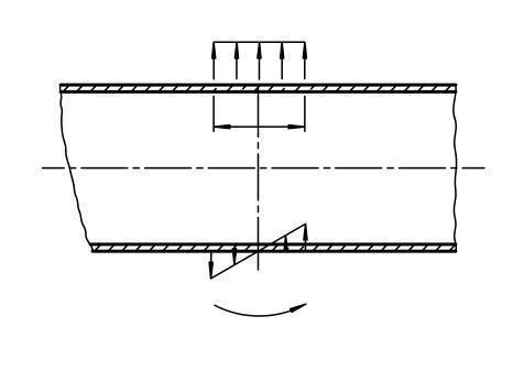
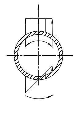
Standard and calculation basis: DIN EN 13445-3/16.6: 2018-12
Calculation workflow
- Define shell type and load direction: First, the shell form is selected (cylindrical shell, torispherical, semi-ellipsoidal or hemispherical end) and it is defined whether the line load acts in the longitudinal or in the circumferential direction of the shell. The two cases lead to different stress distributions.
- Determine the effective shell parameters: From the diameter, the effective wall thickness (after deducting the allowances) and the nominal design stress, the shell parameters that govern the load-bearing capacity against local load introduction are determined.
- Calculate the local membrane and bending stresses: For the applied line force or line moment, the local membrane and bending stress components are calculated according to the relationships of Clause 16.6. The governing factors are the length of the load introduction and its orientation relative to the shell axis.
- Superimpose the pressure stresses: The local stresses are superimposed on the global stresses from the design pressure, since both components act simultaneously at the load introduction point.
- Perform the admissibility check: The superimposed stresses are compared with the allowable values for local primary and secondary stresses. If the check is not satisfied, longer load introduction zones, reinforcing pads or a greater wall thickness will help.
Input quantities
| Quantity | Symbol | Unit |
|---|---|---|
| Equivalent calculation diameter | Deq | mm |
| Inside diameter of cylindrical shell or dished end | Di | mm |
| Inside diameter of conical shell at the center of supporting element | Dk | mm |
| Inside radius of spherical shell or dome of a dished end | Ri | mm |
| Distance between the axis of semi-ellipsoidal head and the centre of the supporting element | x | mm |
| Inside height of a dished head measured from the tangent line | Hi | mm |
| Nominal thickness | en | mm |
| (minimum) design thickness | ea | mm |
| Nominal design stress | f | MPa |
| Design pressure | P | MPa |
| Global additional axial force on a cylindrical, spherical or conical shell | F | N |
| Local radial force on a shell | FL | N |
| Global bending moment of all the external forces relative to the centre of a specific shell cross-section | M | N·mm |
| Local moment on a shell | ML | N·mm |
| Semi-angle at apex of conical shell | α | ° |
| Length of line load | b | mm |
| Geometrical condition | Bed,en/Deq | – |
| Geometrical condition | Bed,bx/Deq | – |
| Load case | Fr,Bed | – |
| Direction of line load | Fr,Last | – |
| Material | WkNr | – |
| Nominal design strength | Re/p/m | N/mm² |
| Safety factor | S | - |
| Wall thickness allowance | c1 | mm |
Calculated results
| Quantity | Symbol | Unit |
|---|---|---|
| Maximum allowable local radial force at shell | FL,max | N |
| \u03bb | λ | - |
| \u03bb1 | λ1 | - |
| \u03bb2 | λ2 | - |
| Maximum allowable local moment at shell | ML,max | N·mm |
| K1 | K1 | - |
| K2 | K2 | - |
| K13 | K13 | - |
| K14 | K14 | - |
| Ratio between local membrane stress and local bending stress | ν1 | - |
| Ratio between global membrane stress and allowable stress | ν2 | - |
| Global membrane stress | σm | MPa |
| Global membrane stress in longitudinal direction | σmx | MPa |
| Global membrane stress in circumferential direction | σmy | MPa |
| Bending stress limit of shell | σb,all | MPa |
| Interaction condition | Fest,lokF,lokM | – |
| Utilization | An,Auslastung | – |
| Stress evaluation | An,Spannung | – |
Calculation options
Direction of line load
Longitudinal direction · Circumferential direction
Show graphics
No · Yes
Type
Cylindrical shell · Conical shell · Spherical shell or dome of torispherical shell · Semi-ellipsoidal head
Frequently asked questions
What is Clause 16.6 for, if there are dedicated clauses for brackets and saddles?
Clause 16.6 provides the basic model of line load introduction into axisymmetric shells. The dedicated checks for support brackets (16.7/16.8), ring supports (16.9) and saddle supports (16.10) build on these relationships. For special cases that deviate from the standard configurations, one can work directly with the line load fundamentals.
What is the difference between a line load in the longitudinal and in the circumferential direction?
For a load in the longitudinal direction, the load introduction line runs parallel to the vessel axis (typical: a vertical support rib on a horizontal vessel); for a load in the circumferential direction it runs transverse to it (typical: the bearing line of a ring or saddle horn). The shell responds with different bending and membrane components in the two cases, which is why the standard provides separate coefficients.
Do the checks also apply to dished ends?
Yes. In addition to the cylindrical shell, the module supports torispherical, semi-ellipsoidal and hemispherical ends. For dished ends, the local load introduction is treated via the equivalent spherical shell in the region considered; the governing quantity is the local radius of curvature at the load introduction point.
What is a typical source of error with local load introductions?
The actually effective load introduction length is frequently overestimated: only the zone where the attachment bears fully against the shell and is welded continuously may be credited. The superposition with the most unfavourable pressure state (internal pressure, vacuum, or the unpressurized state with full attachment loads) is also occasionally overlooked – the most unfavourable combination governs.