Engineering task and calculation objective
The STUT module assesses nozzles on pressure vessels under external loads from connected piping. Piping transmits forces and moments to the nozzle as a result of thermal expansion, dead weight and reaction forces; these loads create local membrane and bending stresses in the transition region between nozzle and vessel wall, which add to the stress from internal pressure. Anyone who needs to calculate nozzle loads and demonstrate that the vessel wall can carry the piping loads reported by the piping stress analysis will find the corresponding strength verification here.
The module covers nozzles on cylindrical shells and on dished ends. From the applied forces (radial force, shear forces) and moments (bending and torsional moments), the existing stress in the attachment region is determined and compared with the allowable stress of the material at design temperature. The result is a clear utilization check: existing stress versus allowable stress, supplemented by comments on the assessment.
In practice, this verification is standard at the interface between vessel fabrication and piping engineering: the piping engineer delivers the nozzle loads from the flexibility analysis, and the vessel manufacturer demonstrates that nozzle and shell can carry these loads in addition to the internal pressure – or requests reduced allowable nozzle loads for the piping design.
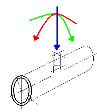
Calculation workflow
- Enter the geometry of shell and nozzle: Inputs are the dimensions of the main body (cylindrical shell or dished end: diameter, wall thickness) and of the nozzle (outside diameter, wall thickness, reinforcement where applicable). The diameter and wall thickness ratios determine the flexibility of the attachment.
- Take over the loads from the piping: The section loads from the piping analysis – axial force, shear forces plus bending and torsional moments at the nozzle connection – are applied for the governing load case, usually together with the internal pressure acting at the same time.
- Calculate the local stresses: For each load component, the local membrane and bending stresses in the vessel wall at the nozzle edge are determined and superimposed with the stresses from internal pressure; the most unfavorable location around the circumference of the attachment governs.
- Compare with the allowable stress: The existing equivalent stress is compared with the allowable stress, which is derived from the material strength value at design temperature and the multiple permitted for local stresses. The result is documented as a utilization ratio with comments.
- Derive the consequences: If the allowable stress is exceeded, remedies must be examined: a reinforcing pad, a thicker nozzle, a larger shell wall thickness in the attachment region, or a reduction of the piping loads by rerouting the line or adding supports.
Input quantities
| Quantity | Symbol | Unit |
|---|---|---|
| Outside nozzle diameter | da | mm |
| Shell radius (outside) | R | mm |
| Outside diameter of basic body | Da | mm |
| Final shell wall thickness | se | mm |
| Wall thickness without | s | mm |
| Normal force | Q | N |
| Moment longitudinal direction | Ml | N·mm |
| Moment circumferential direction | Mu | N·mm |
| Nominal design strength (oper.) | K | N/mm² |
| Nominal design strength (test) | K' | N/mm² |
| Allowable stress | σZ | N/mm² |
| Existing stress | σl | N/mm² |
| Wall thickness allowance | c1 | mm |
| Corrosion / wear allowance | c2 | mm |
| Safety factor (operation) | S | – |
| Safety factor (test) | S' | – |
| Design temperature | T | °C |
| Material | Werkstoffnummer | – |
| Comments | 1 | – |
| 2 | 2 | – |
Frequently asked questions
Where do the nozzle loads I have to enter come from?
Usually from the flexibility or stress analysis of the connected piping (pipe stress analysis). As long as this is not yet available, standard nozzle load tables from the plant owner or from codes are frequently used as a design specification. It is important that load directions and sign convention agree between the pipe stress analysis and the nozzle verification.
Why is the opening reinforcement check for pressure alone not sufficient?
The opening reinforcement check (e.g. per AD 2000 B 9 of the German AD 2000 code, or EN 13445) only covers the weakening of the shell by the opening under internal pressure. Forces and moments from the piping create additional local bending stresses that are not contained in that verification. Heavy, hot lines on thin-walled vessels in particular are often sized by the external loads rather than by the pressure.
What are the limits of such nozzle load calculation methods?
The classical methods (e.g. based on WRC 107/537 or the local load cases in EN 13445-3) apply to limited nozzle-to-shell diameter ratios and require sufficient distance to neighboring discontinuities (other nozzles, welds, supports). For large openings, hillside or angled nozzles, or closely spaced connections, they yield increasingly conservative or unreliable results; an FEM analysis is then indicated.
Do operating and installation load cases have to be considered separately?
Yes. Different combinations may govern: operation with internal pressure, temperature and thermal expansion loads; start-up and shutdown; but also the unpressurized condition with pure installation loads. For time-varying loads, it must additionally be assessed whether the fluctuation range of the local stresses makes a fatigue analysis necessary.