Engineering task and calculation objective
The EN15 module calculates rectangular pressure vessels to DIN EN 13445-3 clause 15. Unlike cylindrical vessels, rectangular boxes carry internal pressure predominantly through plate bending; the walls act as a frame of interconnected plates. For unreinforced and reinforced designs, the module determines the existing membrane and bending stresses at the governing locations, checks the geometric limits of applicability of the standard, and compares the results with the allowable stresses.
Having to calculate a rectangular pressure vessel is typical for air receivers of commercial vehicles, casings of heat exchangers and filters, ducts, sterilizers and autoclaves with a rectangular working chamber. Because flat walls carry pressure inefficiently, the standard provides, in addition to the unreinforced design, reinforcement by welded-on profiles or ribs as well as by stays and partition plates, which shorten the spans of the plates and thus enable economical wall thicknesses.
The calculation to EN 13445-3 clause 15 covers only stresses arising from internal overpressure. Additional loads such as nozzle forces, support reactions or vacuum must be assessed separately.
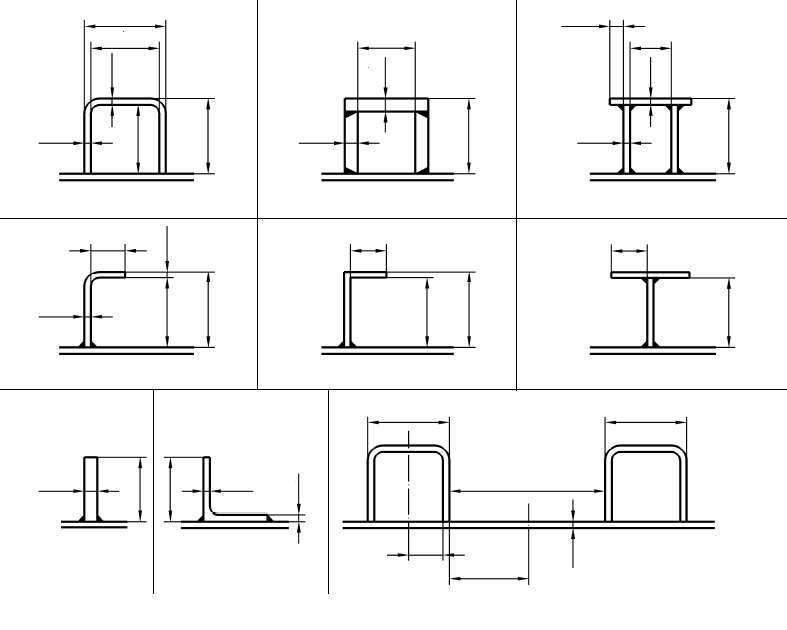
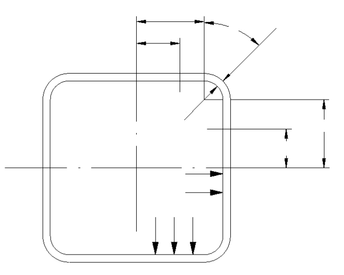
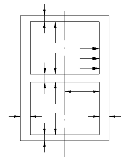
Standard and calculation basis: DIN EN 13445-3/15: 2021-12
Calculation workflow
- Select the design and record the geometry: First, it is established whether the vessel is unreinforced, reinforced with profiles, or fitted with stays or partition plates. Then the cross-section dimensions, wall thicknesses, corner radii and, where applicable, the profile cross-sections and reinforcement spacings are entered.
- Check the limits of applicability: The standard ties its formulas to geometric conditions, for instance limits on aspect ratios and the design of the corners. The module checks these prerequisites before the stress calculation is performed.
- Calculate membrane and bending stresses: For the frame cross-section loaded by internal pressure, the membrane stresses from the circumferential tension and the bending stresses from plate bending are determined at the governing locations, in particular at mid-wall and in the corners. For reinforced vessels, the composite cross-section of wall and profile carries the load.
- Account for openings and welds: Openings in the walls weaken the load-bearing cross-section and are captured via ligament efficiency factors; weld joint factors enter the allowable stresses.
- Perform the stress verification: The calculated stresses are compared with the allowable values: membrane stresses with the nominal design stress, combined membrane plus bending stresses with 1.5 times that value. If the verification is not satisfied, the wall thickness or reinforcement is adjusted and the calculation repeated.
Input quantities
| Quantity | Symbol | Unit |
|---|---|---|
| Inside corner radius | a | mm |
| 2= | 2= | – |
| Net width of all weldings between reinforcement and vessel (thickness + penetration) | bcw1 | mm |
| Inside width of reinforcement (web distance) | bf1 | mm |
| Distance between the center lines of reinforcements | bR1 | mm |
| Mill tolerance | c1 | mm |
| Corrosion allowance | c2 | mm |
| Opening diameter (0=unpierced) or inside diameter of a penetration welded connection at the short side | d1 | mm |
| Nominal wall thickness | ev1 | mm |
| Modulus of elasticity for operation | E | MPa |
| Inside width of the long vessel side | h | mm |
| Inside width of the short vessel side | H | mm |
| Radial height of reinforcement | hr1 | mm |
| Material strength operation | K | MPa |
| Material strength testing | K20C | MPa |
| Half length of the short side to the rounding D-C | l1 | mm |
| Total length of a weld segment | lwS | mm |
| Distance between opening in D-C and vessel center | lx | mm |
| Half length of the long side to the rounding A-B | L | mm |
| Distance between opening in A-B and vessel center | Ly | mm |
| Hole pitch along the plate length Fig. (15.5-2) | p | mm |
| Diagonal hole pitch Fig. (15.5-2) | pS | mm |
| Safety factor operation | S | - |
| Safety factor testing | S20 | - |
Calculated results
| Quantity | Symbol | Unit |
|---|---|---|
| Reinforcement cross section at the short side | A1' | mm² |
| Reinforcement cross section at the short side | A2' | mm² |
| zwische | g1 b1 g1/b1 | mm |
| Shear load at the section close to the corner | Q2 | N |
| Distance between external and neutral fibre (+)inside | c1 | mm |
| Plate dimensions g1, b1 for Table 15.6-2 | C1 | mm |
| Analysis wall thickness | e1 | mm |
| zwischen | g1 b1 g1/b1 | mm |
| Centroid distance of reinforcements | H+2·jA2+ev2 h1 | mm |
| Centroid distance of reinforcements | H+2·jA1+ev1 H1 | mm |
| Second moment of area per unit width of a strip of thickness e1 | I1 | mm^4/mm |
| Second moment of area per unit width of a strip of thickness e e2 | I2 | mm^4/mm |
| Second moment of area of the combined reinforcing member and plate on the short side of the vessel | I11 | mm^4/mm |
| Second moment of area of the combined reinforcing member and plate on the long side of the vessel | I21 | mm^4/mm |
| Centroid distance betw. area A1' and neutral axis | j1 | mm |
| Coefficient acc. to Eq. (15.5.2-3) | = I2/I1·α k | - |
| Coefficient acc. | (15.5.1.2-12) K3 | - |
| Bending moment/unit length, long side face(-)=tension | MA | N |
| Inside pressure for load case | P Pb | MPa |
| Inside pressure for load case | P Pb | bar |
| Shear load at the section close to the corner | Q1 | N |
| Coefficient acc. to Eq. (15.5.2-5) | α | - |
| Coefficient acc. to Eq. (15.5.1.2-13) | α1 | - |
| Coefficient L/l1 | (15.5.1.2-14) α3 | - |
Calculation options
2=
with or without opening · with central partition plate · reinforcement with continuous welding · reinforcement with intermittent welding
2=(a
U-profile (a1) · U-profile (a2) · U-profile (a3) · L-profile (b1) · L-profile (b2) · T-profile (b3) · rectangular massive profile (c1) · L-profile (c2) · user defined
2=(a
U-profile (a1) · U-profile (a2) · U-profile (a3) · L-profile (b1) · L-profile (b2) · T-profile (b3) · rectangular massive profile (c1) · L-profile (c2) · user defined
Product
welded · rolled or cold formed
Product
welded · rolled or cold formed
Frequently asked questions
Why are rectangular pressure vessels so much heavier than cylindrical ones?
A cylinder carries internal pressure almost entirely through membrane tension, whereas a flat wall carries it in bending. The bending stress grows with the square of the span relative to the wall thickness, so unreinforced rectangular vessels quickly require uneconomically thick walls. Reinforcing profiles, stays or partition plates shorten the spans and make the design competitive when the process requires a rectangular cross-section.
Does the calculation to clause 15 also cover vacuum or external loads?
No. The rules of clause 15 deal exclusively with stresses from internal overpressure. For vacuum operation, the stability of the flat walls and reinforcements must be assessed in addition, and external loads from nozzles, supports or piping require separate verifications, for example to clause 16 or via an analysis to Annex C.
Where are the most highly stressed locations of a rectangular vessel?
The governing locations are usually the corner regions of the frame, where large bending moments occur, and the middle of the longer wall, where the span moment is superimposed on the membrane tension. In reinforced vessels, the connections of the reinforcing profiles and the panels between the reinforcements come into play as well. The module evaluates all these locations.
What must be considered with stays and partition plates?
Stays and continuous partition plates act as intermediate supports and reduce the moments in the outer walls considerably. In return, they must safely carry their share of the pressure load and remain permanently connected to the walls. Their connecting welds must be verified accordingly; failure of a stay changes the structural system and must be ruled out by design.