Engineering task and calculation objective
The EN20 module calculates reinforcements for flat walls and circular flat ends to DIN EN 13445-3, clauses 20 and 21. It combines two related tasks: stayed flat walls to clause 20, where stays or stay tubes support the plate at regular intervals, and circular flat ends with radial reinforcement ribs to clause 21, either without a circumferential moment (clause 21.4) or with a circumferential moment (clause 21.5). The applicable calculation clause is selected via the design configuration.
Such reinforced constructions are used where an unreinforced flat plate would become uneconomically thick: stayed walls are classically found in fireboxes, box-shaped vessels and large flat closures; radially ribbed circular ends in large vessel covers, agitator vessels and bolted end covers. The stays or ribs shorten the spans of the plate and carry part of the pressure load, so that considerably smaller plate thicknesses are possible than for unstayed flat ends to clause 10.
Besides the plate, the module also checks the reinforcing elements themselves, for example a centering ring with its material, diameter and thickness, and verifies the operating and test conditions separately. The weld joint factor of the connecting welds enters the allowable stresses.
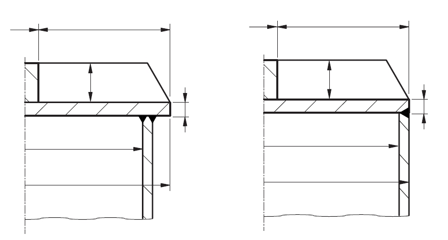
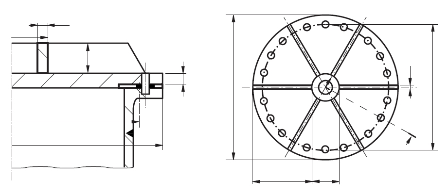
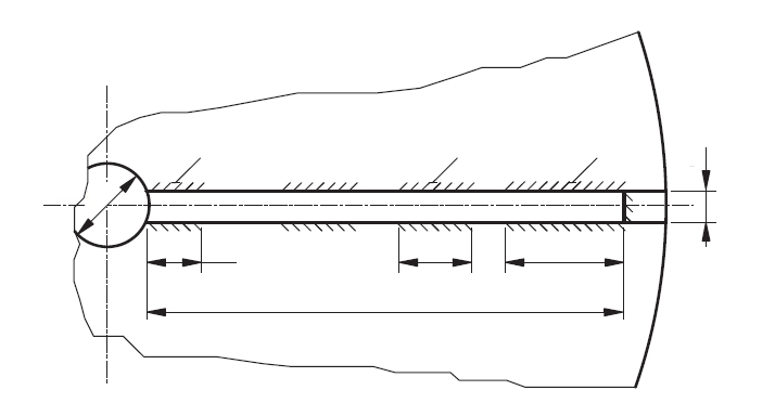
Standard and calculation basis: DIN EN 13445-3/20,21: 2021-12
Calculation workflow
- Select the configuration and calculation clause: First, the configuration is defined: stayed flat wall to clause 20, or circular flat end with radial ribs to clause 21.4 (without circumferential moment) or 21.5 (with circumferential moment, for instance from a bolted edge connection). This fixes the structural model of the calculation.
- Record geometry and materials: The inputs are the plate thickness and dimensions, the arrangement and cross-sections of the stays or ribs, and, where present, a centering ring with diameter, thickness and material. Design pressure and design temperature determine the allowable stresses of the materials involved, for both operation and testing.
- Verify the plate between the supports: The plate is treated as a panel between the stays or ribs. The required plate thickness follows from the span, the pressure and the allowable stress; the standard provides coefficients that represent the clamping effect of the supports.
- Verify the reinforcing elements: Stays and stay cross-sections are verified for their share of the tensile force from the pressure area, radial ribs for bending and shear from the load transfer to the edge. The connection between rib or stay and plate, and any centering ring present, are also checked; the weld joint factor reduces the allowable stress of the connecting welds.
- Evaluate the operating and test load cases: All verifications are performed for the operating condition and the test condition with the respective pressures, temperatures and allowable stresses. The most unfavourable load case governs.
Input quantities
| Quantity | Symbol | Unit |
|---|---|---|
| Head Material | Boden | – |
| Reinforcement ribs Material | Rippe | – |
| Centering ring Material | Zentrierring | – |
| Calculation temperature | T | °C |
| Calculation pressure | P = bar = P | bar |
| Calculation pressure | P = bar = P | MPa |
| Nominal wall thickness | e | mm |
| Outside diameter | d4 | mm |
| Test | K' S' f' | MPa |
| Operation | K S f | MPa |
| Test | K' S' f' | – |
| Operation | K S f | – |
| Wall thinning allowance | c1 | mm |
| Corrosion allowance | c2 | mm |
| Test | K' S' f' | MPa |
| Operation | K S f | MPa |
| Load case | 2=Prüfung | – |
| Test pressure | Pp = bar = Pp | bar |
| Test pressure | Pp = bar = Pp | MPa |
| Geometry | Geometrie | – |
| Diameter (0=no ring) | d1 | mm |
| Pressure loaded diameter | d2 | mm |
| Bolt circle diameter | d3 | mm |
| Thickness | eR | mm |
Calculated results
| Quantity | Symbol | Unit |
|---|---|---|
| Head Material | Boden | – |
| Stay Material | Schrauben | – |
| Reinforcement ribs Material | Rippe | – |
| Centering ring Material | Zentrierring | – |
| Calculation temperature | T | °C |
| Calculation pressure | P = bar = P | bar |
| Calculation pressure | P = bar = P | MPa |
| Nominal wall thickness | e | mm |
| Outside diameter | d4 | mm |
| Pitch | p | mm |
| Stress factor (2.1-3.2) | C | - |
| Test | K' S' f' | MPa |
| Operation | K S f | MPa |
| Test | K' S' f' | – |
| Operation | K S f | – |
| Wall thinning allowance | c1 | mm |
| Corrosion allowance | c2 | mm |
| Test | K' S' f' | MPa |
| Operation | K S f | MPa |
| Head thickness acc. (21.4-4) | emin ≤ | mm |
| Head thickness | er ≤ | mm |
| Pitch | p ≥ | mm |
| Load case | 2=Prüfung | – |
| Head thickness | er ≤ | mm |
Calculation options
Type
Stayed flat walls · Ends without additional peripheral bending moment · Ends with additional peripheral bending moment
Frequently asked questions
When does a ribbed or stayed end pay off compared with a thicker unreinforced plate?
The required thickness of an unreinforced plate grows in proportion to the diameter and to the square root of the pressure. From medium diameters upward, this quickly leads to very heavy plates with high machining and welding effort. Radial ribs or stays shorten the effective spans, so the plate thickness drops drastically. Set against this are additional welding effort and the verifications of the reinforcing elements; the design is economically worthwhile mainly at large diameters and moderate pressures.
What does the distinction with and without circumferential moment mean for circular ends to clause 21?
Without a circumferential moment (21.4), the end rests moment-free at the edge, as with welded ends with a flexible edge connection. With a circumferential moment (21.5), an edge moment acting around the circumference is additionally considered, as typically arises from a bolted flange connection with a narrow-face gasket. The edge moment changes the moment distribution in the plate and ribs considerably and must therefore not be neglected.
What are typical sources of error with stayed walls?
Frequent errors are overlooking the edge panel, which can be larger than the regular stay pitch, neglecting the bending load in the stays when the force does not act perpendicularly, and overly optimistic assumptions about the clamping of the plate at the stays. The connecting welds of the stays must also transfer the full stay force; their weld joint factor and inspectability must be chosen accordingly.
Does the verification to clauses 20/21 replace the opening reinforcement check for openings in the end?
No. Openings in reinforced ends or walls interrupt the plate and possibly the ribs and must be assessed separately. Small openings between the reinforcements can often be covered by the rules for flat ends; larger openings that cut through ribs or stays require a structural rerouting of the forces and, in case of doubt, a case-by-case analysis.