Engineering task and calculation objective
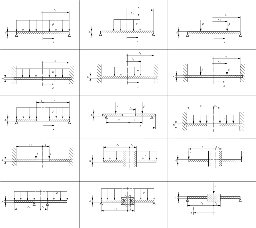
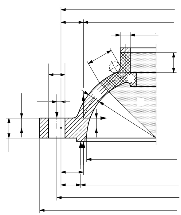
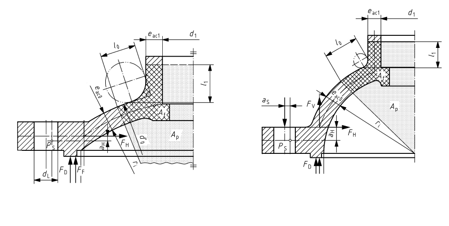
Module 12516C calculates dished ends, spherical shells per clause 8.3, and circular plates and annular plates for valve bodies to DIN EN 12516-2. Typical applications are covers made of a spherical shell with an adjoining flange, dished body closures and flat cover plates of globe and gate valves under internal pressure.
To calculate a dished end to DIN EN 12516-2 means verifying the required wall thickness separately for the knuckle and the spherical crown — the knuckle is covered via the calculation coefficient (shape factor), the crown is treated as a spherical shell with the inside crown diameter. The module determines both wall thicknesses for the operating and the test condition, compares them with the as-built thicknesses, and additionally checks the required straight-flange height and the decay lengths for equal or unequal wall thickness.
Material properties, safety factors and the weld joint efficiency enter the calculation, as do the allowances for wall thickness undertolerance and for corrosion/wear, so the verifications can be used directly for design and re-rating in valve engineering.
Standard and calculation basis: DIN EN 12516-2: 2022-08
Calculation scope
- Spherical shell with adjacent flange
- Dished heads
- Flat circular plates and ring plates
- Ring plates acc. to aplication case I
- Ring plates acc. to aplication case II
Calculation workflow
- Define end type and geometry: First the end type (torispherical, semi-ellipsoidal or spherical cap with flange), the outside diameter, the as-built wall thicknesses of knuckle and crown and the as-built straight-flange height are entered.
- Determine material and load data: From the material and the design temperature follow the strength values for operation and test; together with the safety factors, the weld joint efficiency and the allowances for wall thickness undertolerance and corrosion, the allowable stresses are established.
- Determine the knuckle calculation coefficient: The calculation coefficient (shape factor) captures the bending stress in the knuckle; it depends on the end shape and the ratio of wall thickness to diameter and enters the required knuckle thickness directly.
- Calculate required wall thicknesses: For the operating and test conditions, the required wall thicknesses of the knuckle and — via the crown diameter ratio — of the spherical crown are calculated and compared with the as-built wall thicknesses.
- Check straight-flange height and decay lengths: Finally the module checks the required cylindrical straight-flange height as well as the decay lengths for equal and unequal wall thickness, within which discontinuity stresses from the knuckle region must have died out.
Input quantities
| Quantity | Symbol | Unit |
|---|---|---|
| Required knuckle wall thickness Operation | Krempe | mm |
| Required crown wall thickness Operation | Kalotte | mm |
| Outside diameter | d0 | mm |
| Diameter of centre of gravity | dp | mm |
| Design pressure | p | bar |
| Design pressure | p | N/mm² |
| Nominal design strength Operation | K | N/mm² |
| Safety factor Operation | S | – |
| Joint efficiency factor | k | – |
| wall thickness allowance | c1 | mm |
| Corrosion allowance | c2 | mm |
| Run-out length (equal thickness) | x | mm |
| Shape factor | β | – |
| Final knuckle wall thickness | ecK | mm |
| Final crown wall thickness | ec | mm |
| Final skirt height | h | mm |
| Test pressure | p' | N/mm² |
| Type of head Press F7 after change | Bodenart | – |
| Operation | ≤ | N/mm² |
| Test | ≤ | N/mm² |
| Run-out length (different wall thickness) | x | mm |
| Safety factor Test | S | – |
| Nominal design strength Test | K | N/mm² |
| Test pressure | p' | bar |
Calculated results
| Quantity | Symbol | Unit |
|---|---|---|
| Operation | ≤ | N/mm² |
| Test | ≤ | N/mm² |
| Operation | ≤ | N/mm² |
| Test | ≤ | N/mm² |
| Installation | ≤ | N/mm² |
Calculation options
Consider Additional force due to internal pressure)
No · Yes
Evaluation with actual wall thickness at transition
No · Yes
Frequently asked questions
Why are knuckle and crown verified separately?
The crown is in an almost pure membrane stress state like a spherical shell, whereas the knuckle carries additional bending stresses from the change in curvature. The knuckle therefore receives a higher computational loading via the calculation coefficient; depending on the geometry, either the knuckle or the crown can yield the larger required wall thickness.
What is the purpose of the cylindrical straight flange on a dished end?
The straight flange moves the weld to the adjoining component out of the bending-loaded knuckle region into the membrane-loaded cylindrical part. The standard therefore requires a minimum straight-flange height; the module compares the as-built with the required height.
What does the decay length mean for unequal wall thicknesses?
Discontinuity stresses at the transition between components of different stiffness die out only over a certain length. Within this decay length no further discontinuities such as steps in wall thickness or openings may be located. For unequal wall thickness of end and adjoining part, a different decay length applies than for equal thickness — the module reports both.
Does the calculation also cover test conditions?
Yes. The module runs the verification in parallel for the operating condition with the design pressure and for the test condition with the test pressure, each with the corresponding strength values and safety factors. The condition yielding the larger required wall thickness governs.