Engineering task and calculation objective
Calculating the wall thickness of straight pipes under internal pressure is the fundamental task of any piping design to the European code. This module calculates piping components to DIN EN 13480-3, clause 6: straight pipes, pipe bends and elbows, mitre bends, conical shells, and reducers including the transitions at the large and the small end — with and without a knuckle.
For each component selected via the design type, the module determines the required minimum wall thickness from design pressure, diameter, nominal design stress and joint efficiency. For pipe bends, the wall thickness is determined separately at the intrados and extrados, since the stress distribution across the bend cross-section is non-uniform; for mitre bends and reducers, additional geometry-dependent conditions apply.
The calculation is needed both when designing new piping classes and when verifying existing lines: calculate the pipe wall thickness to EN 13480, apply allowances for corrosion and manufacturing tolerances, and select the appropriate nominal wall thickness from the available product range.
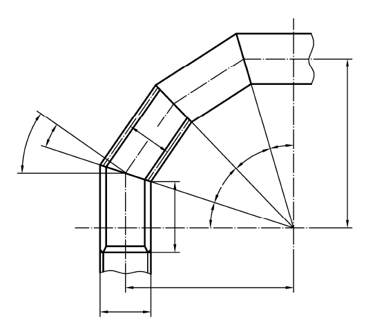
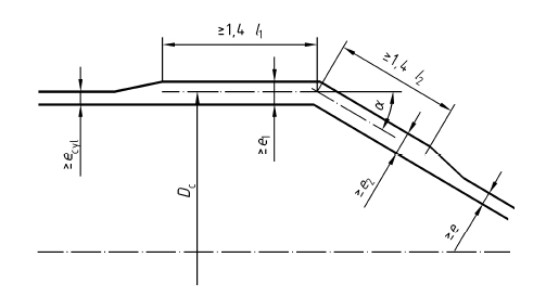
Standard and calculation basis: DIN EN 13480-3/6: 2017-12
Calculation scope
- Straight pipes and pipe bends
- Segmental bends
- Conical shells
- Large end of a reduction without knuckle
- Large end of a reduction with knuckle
- Small end of a reduction
Calculation workflow
- Select the component type: The component is defined via the design-type variable: straight pipe, pipe bend or elbow, mitre bend, conical shell, or reducer (large end with or without knuckle, small end). The design type controls which equations of clause 6 of DIN EN 13480-3 are applied.
- Determine design data and nominal design stress: The inputs are design pressure, design temperature, pipe dimensions and material. The nominal design stress f is obtained from the yield strength at design temperature and the tensile strength using the safety factors of the code; the joint efficiency z accounts for the manufacture of longitudinally welded pipes (z = 1 for seamless pipes).
- Calculate the minimum wall thickness: For the straight pipe, the required wall thickness is determined from the code's boiler formula. For bends, a correction based on the bend radius follows: a larger wall thickness is required at the intrados, a smaller one at the extrados, compared with the straight pipe. For conical shells and reducers, the half apex angle and the transition geometry enter the calculation.
- Apply allowances: The corrosion or abrasion allowance and the manufacturing minus tolerance of the product (for bends additionally the thinning during bending) are added to the calculated minimum wall thickness. Only the ordering wall thickness determined this way should be compared with the available wall thickness range.
- Check the nominal wall thickness: The selected nominal wall thickness is checked against the requirement: nominal wall thickness minus all allowances and tolerances must reach the required minimum wall thickness at every point of the component. The module reports the utilization and enables a quick comparison of several piping classes.
Input quantities
| Quantity | Symbol | Unit |
|---|---|---|
| Load case | 2=Pruefung) | – |
| Required reinforcement thickness for | Lastfall | – |
| Operating temperature | t | °C |
| Operating pressure | Pmax = ≥ | MPa(p) |
| Material designation | Werkstoffbezeichnung | – |
| Wall thickness manufacturing allowance | δe | mm |
| Corrosion allowance | c | mm |
| Thickness reduction after forming | δm | mm |
| Sum of allowances | Σ(δ) | mm |
| Effective bending radius (only for V=1) | R | mm |
| Inside: | eaint ≥ eint | mm |
| Outside: | eaext ≥ eext | mm |
| Festigkeitsbedingung | Festigkeitsbedingung | – |
| Allowable stress | f f' | N/mm² |
| (or given) inside diameter | Di | mm |
| Final wall thickness acc. drawing | encyl | mm |
| Strength | (Re, Rp, Rm) K K' | N/mm² |
| Safety factor | S S' | – |
| Strength | (Re, Rp, Rm) K K' | N/mm² |
| Safety factor | S S' | – |
| Testing pressure | P'max = ≥ | MPa(p) |
| Required wall thickness | eb e' | mm |
| Welding factor acc. 4.5: (1, 0.85, 0.7) | z | – |
| unreinforced | eacyl ≥ ecyl | mm |
Calculated results
| Quantity | Symbol | Unit |
|---|---|---|
| Operating pressure | Pmax = ≥ | MPa(p) |
| Inside: | eaint ≥ eint | mm |
| Outside: | eaext ≥ eext | mm |
| Festigkeitsbedingung | Festigkeitsbedingung | – |
| Allowable stress | f f' | N/mm² |
| Testing pressure | P'max = ≥ | MPa(p) |
| Required wall thickness | eb e' | mm |
| unreinforced | eacyl ≥ ecyl | mm |
| Allowable stress | f f' | N/mm² |
| Operation | Pmax = ≥ | MPa(p) |
| Required wall thickness | eb e' | mm |
| Bedingungen | : | – |
| with allowances | eδ | mm |
| for operation for testing | pa1 = pa1' = | MPa(p) |
| (6.3.4-2) only for V=1 | pa2 pa2' | MPa(p) |
| unreinforced | eacyl ≥ ecyl | mm |
| Required thickness without allowances | (eaco > ) e | mm |
| Outside: | eaext ≥ eext | mm |
| Inside: | eaint ≥ eint | mm |
| Inside, operation | fint ≤ f | N/mm² |
| Inside, testing | fint' ≤ f' | N/mm² |
| Outside, operation | fext ≤ f | N/mm² |
| Outside, testing | fext' ≤ f' | N/mm² |
| for operation for testing | pa1 = pa1' = | MPa(p) |
Calculation options
Bauform
Straight pipe acc. 6.1 · Standard calculation method for pipe elbows acc. 6.2.3.1 · Alternative calculation method for pipe elbows acc. 6.2.3.2 · Accurate calculation method for pipe elbows of constant thickness · Accurate calculation method for pipe elbows acc. Appendix B
Type
6.1 Straight pipes and 6.2 pipe bends and elbows · 6.3 Segmental bends · 6.4.4 Conical shells · 6.4.6 Large end of a reduction without knuckle · 6.4.7 Wide end of a conical reducer with knuckle · 6.4.8 Small end of a reduction
Type
Multiple miters · Single miter
Worked example
For a DN 200 steam line, the required wall thickness of a straight, seamless pipe is to be determined to DIN EN 13480-3, clause 6 — a worked example for calculating pipe wall thickness to EN 13480. Design pressure 40 bar (4.0 MPa) at 200 °C, material P265GH to EN 10216-2.
Given values
| Outside diameter Do | 219.1 mm |
| Design pressure p | 4.0 MPa (40 bar) |
| Design temperature | 200 °C |
| Material | P265GH (seamless, z = 1.0) |
| Corrosion allowance c0 | 1.0 mm |
| Minus tolerance of product | 12.5% |
Solution
Determine the nominal design stress
For P265GH at 200 °C the minimum yield strength is Rp0.2/200 °C = 192 MPa; the tensile strength at room temperature is Rm = 410 MPa. The nominal design stress is the smaller of Rp0.2/T/1.5 and Rm/2.4:
f = min(192/1.5; 410/2.4) = min(128.0; 170.8) = 128 MPa
Minimum wall thickness from the boiler formula
For straight pipes, referred to the outside diameter, DIN EN 13480-3 gives:
e = p · Do / (2 · f · z + p)
e = 4.0 · 219.1 / (2 · 128 · 1.0 + 4.0) = 876.4 / 260 = 3.37 mm
Limit of applicability: with a nominal wall thickness of 6.3 mm, Do/Di = 219.1/206.5 = 1.06 ≤ 1.7 — the thin-wall formula is permissible.
Check the nominal wall thickness with allowances
The standard wall thickness of 6.3 mm is selected. After deducting the minus tolerance of 12.5% and the corrosion allowance, the remaining load-bearing wall thickness is:
eavail = 6.3 · 0.875 − 1.0 = 4.51 mm ≥ 3.37 mm
The strength condition is satisfied; the 219.1 × 6.3 mm pipe is adequately sized for 40 bar at 200 °C.
Result
| Nominal design stress f | 128 MPa |
| Required minimum wall thickness e | 3.37 mm |
| Selected nominal wall thickness | 6.3 mm (load-bearing 4.51 mm) |
All values are illustrative. The applicable standard and project-specific boundary conditions remain authoritative.
Frequently asked questions
Up to which wall thickness ratio do the simple wall thickness formulas apply?
The basic equations of clause 6 apply to thin-walled pipes; DIN EN 13480-3 limits their application via the ratio of outside to inside diameter (Do/Di ≤ 1.7). For thicker-walled pipes, the code provides separate relationships, since the stress distribution across the wall can then no longer be assumed to be constant.
Why does the intrados of a pipe bend need a larger wall thickness than the straight pipe?
In the bend, the circumferential stress is unevenly distributed across the cross-section: the stresses concentrate at the intrados, and are lower at the extrados. The code therefore corrects the wall thickness with a factor depending on the ratio of bend radius to pipe diameter. Conveniently, in practice, pipe bending thins the extrados and thickens the intrados — so manufacturing works in the right direction; it still has to be verified, though.
Which allowances must be considered between the calculated minimum wall thickness and the ordering wall thickness?
Three components: the corrosion/erosion allowance c0 according to medium and service life, the minus tolerance of the product (for seamless pipes to EN 10216 typically 12.5% of the nominal wall thickness), and manufacturing-related wall thickness losses such as thinning during bending. Anyone who orders only the calculated minimum wall thickness will almost inevitably fall below the required wall thickness in service.
When is a mitre bend permissible instead of an induction-bent elbow?
Mitre bends (bends welded up from mitre-cut segments) are permitted by DIN EN 13480-3, but are subject to their own rules: the allowable pressure depends on the mitre angle per segment and on the effective bend radius, and at larger angles the sustainable pressure drops significantly. For high pressures and cyclic loading, smooth bends are preferable; mitre bends are economical mainly at large nominal sizes and moderate pressures.