Engineering task and calculation objective
The BV29 module calculates tubesheets, covers and the associated bolted connections of shell-and-tube heat exchangers to TGL 32903/29. It covers the split design with a separate tubesheet and bolted cover as well as channels of integral (non-split) construction; in addition, the elasticity coefficient to ST RGW 3649-82 can be determined, which describes the interaction of tubesheet, tube bundle and shell.
The TGL 32903 series is the pressure vessel code of the former East Germany (GDR) and is needed today primarily for the re-rating and assessment of existing plants that were originally designed to TGL. Anyone who needs to calculate a tubesheet to TGL 32903/29, or to verify an older unit as part of periodic inspection, will find here the code-compliant implementation of the original calculation sheets. For new designs, EN 13445, the German AD 2000 code or ASME Section VIII are generally used today.
Typical applications are modifications, upgrades and remaining-life assessments of heat exchangers in existing chemical and power plants, where the original design calculation has to be reproduced.
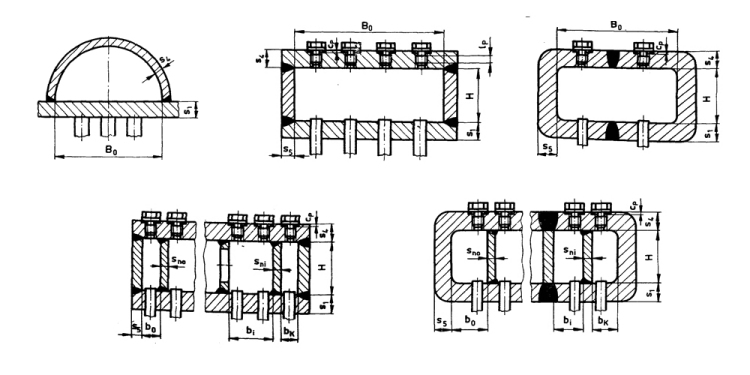
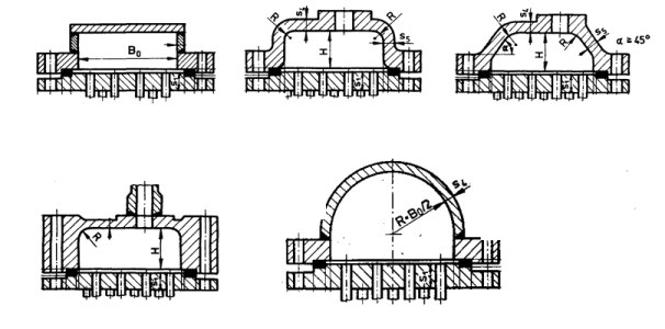
Standard and calculation basis: TGL 32903/29
Calculation scope
- Tubesheets and bolts (split design)
- Covers (split design)
- Chambers of unsplit design
- Elasticity factor according to ST RGW 3649-82
Calculation workflow
- Select the design type: First the design type is chosen: split construction with a tubesheet and a bolted-on cover, or an integral (non-split) channel. The design type determines which calculation sheets of TGL 32903/29 apply and how gasket and bolt forces are accounted for.
- Enter loads and boundary conditions: Design pressure, temperature and the gasket geometry are specified. In the split design, the bolted joint introduces additional edge moments on the tubesheet, which enter the strength verification.
- Determine the elasticity coefficient: The elasticity coefficient is determined according to ST RGW 3649-82; it captures the supporting effect of the expanded or welded-in tube bundle on the tubesheet. It reduces the effective bending load on the perforated plate.
- Verify tubesheet and cover thickness: From pressure, boundary conditions, the ligament efficiency of the perforated area and the allowable stress, the required wall thickness of tubesheet and cover is obtained and compared with the actual thickness.
- Verify the bolted connection: For the bolted joint, the bolt loads are determined for the assembly, operating and test conditions, and the required bolt cross-sections are compared with those actually provided.
Input quantities
| Quantity | Symbol | Unit |
|---|---|---|
| Weld thickness for the tube welding | aT | mm |
| Width of the external chamber sections | b0 | mm |
| Width of the external chamber sections | bK | mm |
| Width of the internal chamber sections | bi | mm |
| Width of the chamber section i + 1 | bi+1 | mm |
| Width of the gasket | bp | mm |
| Design width of the gasket | bPR | mm |
| Sum of all allowances of the tubesheet wall thickness | c | mm |
| Depth of sealing grooves in the perforated back wall | cp | mm |
| Type of attachment (screws = 1 / bolts = 2) | Befestigung | – |
| Effective diameter of the bore-holes in the tubesheet | dE | mm |
| Diameter of bore-holes i-th baffle/pass partition wall | dni | mm |
| Design diameter of the tapped hole for the lock bolts | dPR | mm |
| Outside tube diameter | dT | mm |
| Lever arm for the bending moment | e1 | mm |
| Gasket thickness | hP | mm |
| Factor for the jointed plate | f1 | – |
| Factor for the jointed plate | f4 | – |
| Factor for the fixed plate | f2 | – |
| Factor for plates fixed on the long side | f3 | – |
| Length of the rolled-in slug | l0 | mm |
| Screw / bolt length | lB | mm |
| Distance between the bores in the i-th baffle | lni | mm |
| Screw-in length of the lock bolt | lp | mm |
Calculated results
| Quantity | Symbol | Unit |
|---|---|---|
| Weld thickness for the tube welding | aT | mm |
| Width of the gasket | bp | mm |
| Design width of the gasket | bPR | mm |
| Sum of all allowances of the tubesheet wall thickness | c | mm |
| Effective diameter of the bore-holes in the tubesheet | dE | mm |
| Outside tube diameter | dT | mm |
| Lever arm for the bending moment | e1 | mm |
| Lever arm for bending moments | e1 e2 | mm |
| Length of the rolled-in slug | l0 | mm |
| Gasket factor according to TGL 32903/13 | m | – |
| Number of screws/bolts | n | – |
| Design pressure | p | MPa |
| Test pressure | pnp | MPa |
| Pitch of bore-holes for tubes in longitudinal direction | t1 | mm |
| Pitch of bore-holes for tubes in cross direction | t2 | mm |
| Owing to the strength of the tubes | qT | MPa |
| Owing to attachment | qS | MPa |
| Required thickness of the tubesheet in the tube area | s1 | mm |
| Required wall thickness of the tubesheet in the gasket region | s2 | mm |
| Required thickness of the tubesheet outside the gasket region | s3 | mm |
| Tube wall thickness | sT | mm |
| Number of tube rows in cross direction | z | – |
| Factors | zM zF | – |
| Factors | zM zF | – |
Calculation options
Type
4.1/2 Verification for tube plates and bolts · 4.3 Calculation of the cover · 5. Chamber design for non-divided constuction · Elastic factor according to ST RGW 3649-82
Frequently asked questions
May I still design a new heat exchanger to TGL 32903/29?
For new designs within the scope of the Pressure Equipment Directive, the TGL standards are no longer a harmonized basis; EN 13445, the AD 2000 code or ASME Section VIII are the usual choices. The TGL calculation, however, remains the method of choice when existing equipment that was originally designed and documented to TGL has to be re-rated, assessed or modified — only in this way can the original design be reproduced consistently.
What distinguishes the split design from the integral design?
In the split design, the tubesheet and the channel cover are separate components, bolted together with a gasket. This allows the channel to be opened for cleaning, but introduces additional bolt and gasket forces as well as edge moments on the tubesheet. In the integral design, the channel is permanently connected to the tubesheet, which simplifies the calculation but restricts access.
What is the role of the elasticity coefficient to ST RGW 3649-82?
The elasticity coefficient describes how strongly the tube bundle elastically supports the tubesheet. A stiff bundle acts like a distributed elastic foundation and relieves the plate, so that smaller tubesheet thicknesses can be verified. If it is neglected, the calculation conservatively treats the perforated plate as freely spanning, and considerably larger required thicknesses result.