Engineering task and calculation objective
Vessels under vacuum, jacketed apparatus with a heated annulus, and columns subject to external pressure do not fail by bursting but by buckling of the shell. This module performs the stability verification to DIN EN 13445-3, clause 8, supplemented by the requirements of DIN EN 14025 for dangerous goods tanks: unstiffened cylindrical shells, cylinders with light and heavy stiffeners, conical shells, cone-cylinder junctions, and spherical shells under external pressure.
The verification combines two failure limits: the limit pressure at which the circumferential stress reaches the yield strength, and the theoretical elastic buckling pressure, which depends on the modulus of elasticity, wall thickness, radius, unstiffened length and the circumferential wave number of the buckling mode. Via the buckling curve of the code — which captures the influence of imperfections — and the safety factor of clause 8.4.4, the allowable external pressure is obtained. Since real shells are never perfectly round, the module additionally checks the allowable out-of-roundness.
If you want to calculate a cylindrical shell under external pressure to EN 13445 — for instance for the vacuum design of a vessel or the sizing of stiffening rings — this module delivers the complete buckling verification including all intermediate quantities from circumferential strain to buckling wave number.
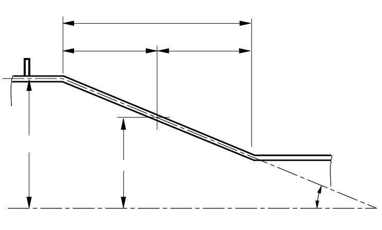
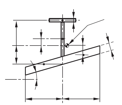
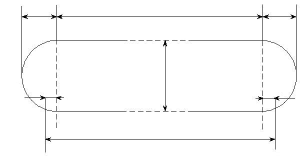
Standard and calculation basis: DIN EN 13445-3/8: 2021-12 & DIN EN 14025: 2018-09
Calculation scope
- Unstiffened cylinders under external pressure
- Cylindrical shells with light stiffeners under external pressure
- Cylindrical shells with heavy stiffeners under external pressure
- Conical shells under external pressure
- Cone-cylinder intersections under external pressure
- Spherical shells under external pressure
Calculation workflow
- Define geometry and allowances: The inputs are the shell form (cylinder, cone, sphere, cone-cylinder junction), diameter, nominal wall thickness and the unstiffened length between effective supports (heads, flanges, stiffening rings). From the nominal wall thickness, the wall thickness undertolerance, corrosion allowance and forming loss are deducted — the buckling verification is carried out with this reduced wall thickness, since it is extraordinarily sensitive to wall thickness.
- Provide material properties: Required are the modulus of elasticity, Poisson's ratio and the 0.2% proof strength at operating temperature; for austenitic steels, different approaches apply for the allowable elastic limit because of the early onset of non-linear material behaviour. All properties are applied at design temperature.
- Determine the limit pressure for yielding: First, the pressure Py is calculated at which the mean circumferential stress of the shell reaches the governing elastic limit. It characterizes the plastic failure of short, thick-walled shells and serves as the reference quantity for the buckling curve.
- Calculate the theoretical buckling pressure: The elastic buckling pressure Pm is determined for the most unfavourable circumferential wave number of the buckling mode — the module varies the wave number and reports the governing one. Input quantities are the modulus of elasticity, the wall-thickness-to-radius ratio and the unstiffened length; for cones an equivalent cylinder is used, for spherical shells the spherical buckling formula.
- Derive the allowable pressure via the buckling curve: From the ratio Pm/Py, the buckling curve of the code (via the circumferential strain at collapse) delivers the sustainable pressure Pr, which accounts for real initial dents and residual stresses. Division by the safety factor of clause 8.4.4 gives the allowable external pressure, which is compared with the applied external pressure.
- Check out-of-roundness and stiffeners: Finally, it is checked whether the out-of-roundness of the fabricated shell lies within the allowable tolerance on which the verification is based. If the allowable pressure is insufficient, light or heavy stiffening rings can be introduced to shorten the unstiffened length; the module also verifies their required stiffness.
Input quantities
| Quantity | Symbol | Unit |
|---|---|---|
| Load case | case | – |
| Calculation temperature | t | °C |
| Calculation pressure | P | MPa |
| Material designation | cylinder | – |
| Wall thinning allowance | δe | mm |
| Corrosion allowance | c2 | mm |
| Thinning allowance during manufacturing | δm | mm |
| Total allowance | ∑(δ) | mm |
| Material strength | RK | N/mm² |
| Curvature deviation greater than 30%? | 2=nein) | – |
| Nominal wall thickness | en | mm |
| based on a max. arc length of measuring range | Bog | mm |
| Combined cross sectional area of stiffened shell | Ae | mm² |
| Cross sectional area of the flange | Af | mm² |
| Modified area of stiffener | (8.5.3-17) Am | mm² |
| Cross sectional area of stiffener | AS | mm² |
| Cross sectional area of the web | Aw | mm² |
| Radial height of the profile | d | mm |
| maximum radius of curvature | RKmax | mm |
| Thickness of the profile flange | ef | mm |
| Analysis web thickness | ew | mm |
| External height of dished end 1 | h' | mm |
| External height of dished end 2 | h'' | mm |
| Area moment of shell and stiffener | Ie | mm^4 |
Calculated results
| Quantity | Symbol | Unit |
|---|---|---|
| Load case | case | – |
| Calculation pressure | P | MPa |
| The strength condition is | Pzul | – |
| Modified area of stiffener | (8.5.3-17) Am | mm² |
| Number of circumferential buckling waves | ncyl | – |
| Theoretical elastic buckling pressure | pm | MPa |
| Limit pressure for circumferential yield | (8.5.3-15) py | MPa |
| Limit pressure for circumferential yield | pys | MPa |
| Strain at collapse | ε | – |
| Max. stress in the stiffener | σs | MPa |
| Parameter | π · R/L Z | – |
| Ratio | pm/py | – |
| Ratio | pr/py | – |
| Analysis wall thickness | ea | mm |
| Factor | (8.5.3-19) δ | – |
| Factor | (8.5.3-40) dquer | – |
| Allowable pressure | (pr/S) pall | MPa |
| Condition (8.5.3-41) is: | 0 < σs < σes = | – |
| Condition | P = < = pr/S | – |
| Allowable out-of-roundness | (8.5.1-1) | -- |
Calculation options
Curvature deviation greater than 30%?
Yes · No
Austenitic steel?
Yes · No
Austenitic steel?
Yes · No
Austenitic steel?
Yes · No
Tee-profile acc. to Fig. 8.6-1,
Yes · No
a) Stiffener with rectangular profile?
Yes · No
c) Heavy stiffener with rectangular profile?
Yes · No
Light or heavy stiffener?
Light stiffener · Heavy stiffener
Frequently asked questions
Why is the allowable out-of-roundness so important in the external pressure verification?
The buckling curve of EN 13445-3 assumes a limited shape deviation — usually 0.5% out-of-roundness. A more oval shell experiences additional circumferential bending stresses under external pressure that trigger buckling considerably earlier; the real collapse pressure can then lie well below the calculated one. Checking the fabricated geometry is therefore always part of the calculation, and the module reports the allowable out-of-roundness explicitly.
What distinguishes light from heavy stiffeners?
Light stiffening rings subdivide the shell into shorter buckling fields and must have sufficient bending stiffness to do so; however, they can fail together with the shell in an overall buckling mode and are verified accordingly. Heavy stiffeners (e.g. heads, tubesheets, massive rings) count as non-displaceable round supports and fully bound the buckling mode. The classification decides which unstiffened length and which verification must be applied.
Why are austenitic steels treated separately in the buckling verification?
Austenitic steels such as 1.4571 have no pronounced yield point and deviate from linear-elastic behaviour well below the 0.2% proof strength. Since the buckling pressure in the elastic-plastic transition region depends sensitively on the tangent modulus, the code applies a reduced allowable elastic limit for these materials. The module therefore explicitly queries the material class.
Must a vessel that can only experience negative pressure during draining be designed for full vacuum?
If the negative pressure is not reliably prevented — for instance by adequately sized venting — design for the maximum possible external pressure is required, in the limiting case full vacuum (1 bar). Frequent causes are condensation of steam after shutdown, pumping out with closed venting, or a sudden temperature drop. The decision is part of the safety assessment; the buckling verification itself is then carried out with this module.