Engineering task and calculation objective
The ENTP module calculates vertical cylindrical or conical vessels on bracket supports to DIN EN 13445-3 clause 16.10. Brackets are local support lugs welded to the shell, by which the vessel rests on structural steel columns or on brackets of the supporting structure; they can be designed with or without a reinforcing plate. The verification ensures that the forces introduced locally into the shell by the brackets do not overstress the vessel wall.
Besides the dead weight of the filled vessel, the calculation takes into account vertical and horizontal additional loads, for example from wind and earthquakes, as well as additional forces and moments on the vessel. From the global axial force, the horizontal force and the global moment at the governing cross-section, the vertical and horizontal force of the single, most unfavourably loaded bracket is determined. Via the equivalent lever arm, this produces the local bending moment which the bracket introduces into the shell.
The allowable bracket force follows from the bending stress limit of the shell, which the standard derives from geometrical factors (including those of equations 16.6-6, 16.6-7 and 16.10-4) and the global membrane stress from pressure and longitudinal force. The verification of local load introductions to clause 16 is thus the counterpart to the pure pressure design of the shell: it is needed for practically every bracket-supported vessel in plant engineering, from the agitator vessel in a steel structure to the small vessel on brackets.
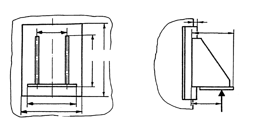
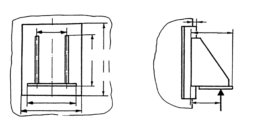
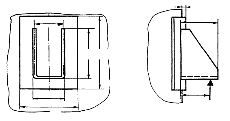
Standard and calculation basis: DIN EN 13445-3/16.10: 2018-12
Calculation workflow
- Record the geometry of vessel and brackets: The inputs are the shell diameter, wall thickness and material of the cylindrical or conical vessel, and the number, dimensions and elevation of the brackets, each with or without a reinforcing plate. The reinforcing plate enlarges the effective load introduction area and increases the allowable bracket force.
- Determine the global loads: From dead weight, contents, attachments and wind and earthquake loads, the global axial force, the horizontal force and the global moment at the centre of the cross-sectional area at the bracket elevation are determined. Additional external forces and moments on the vessel can be superimposed.
- Calculate the forces on the individual bracket: The global internal forces are distributed to the individual brackets; the most unfavourably loaded bracket governs. Its vertical force follows from the axial force and the moment, its horizontal force from the global transverse load. With the equivalent lever arm, the bending moment introduced into the shell is obtained.
- Determine the allowable bracket force: From the geometrical factors of the standard (including 16.6-6, 16.6-7 and 16.10-4), the global membrane stress of the shell and the bending stress limit, the allowable force of one bracket is calculated. The factors capture the ratio of bracket dimensions, shell radius and wall thickness as well as the interaction between local bending and global membrane loading.
- Perform the verification and check the load cases: The existing bracket force is compared with the allowable bracket force for all load cases, including wind and earthquake combinations. The module also checks the geometric limits of applicability of the method. If the verification is not satisfied, reinforcing plates, larger brackets, more brackets or a thicker shell will help.
Input quantities
| Quantity | Symbol | Unit |
|---|---|---|
| Calculation temperature | t | °C |
| Test pressure | P | MPa |
| Material | Behälters | – |
| Mill tolerance | c1 | mm |
| Corrosion allowance | c2 | mm |
| Material strength | KB | N/mm² |
| Material strength | KP | N/mm² |
| Safety factor | SB | – |
| Safety factor | SP | – |
| Allowable stress | fB | N/mm² |
| Allowable stress | fP | N/mm² |
| Modulus of elasticity | EB | N/mm² |
| Modulus of elasticity | EP | N/mm² |
| Material density | ρ | kg/m³ |
| Nominal design stress | f | N/mm² |
| Weld factor | z | - |
| Height of bracket | h1 | mm |
| Width of supporting plate | b1 | mm |
| Height of reinforcement plate | b3 | mm |
| Inside diameter | Di | mm |
| Diameter of conical shell | Dk | mm |
| Angle of conical shell | α | ° |
| Angle of conical shell | αrad | - |
| Equivalent diameter | Deq | mm |
Calculation options
Type of bracket support
1 · 2 · 3 · 4
Reinforcement plate
No · Yes
Frequently asked questions
Why is the pressure design of the shell not sufficient when the vessel rests on brackets?
Brackets introduce forces into the shell at discrete points and generate local bending stresses there, which are superimposed on the membrane stress from the pressure. These local stresses can amount to a multiple of the membrane stress and are not captured by the pure wall thickness calculation to clause 7. The verification to clause 16.10 limits precisely this local loading and frequently decides the required wall thickness in the bracket region.
When should a reinforcing plate be provided under the bracket?
A reinforcing plate distributes the bracket force over a larger shell area and increases the allowable bracket force considerably. It is recommended for thin-walled shells, high support loads, additional horizontal forces, and generally whenever the verification does not work out without a plate. The requirements on the dimensions and connecting welds of the plate must be observed; on vessels subject to fatigue loading, the weld ends must be detailed with particular care.
How are wind and earthquake loads distributed to the individual brackets?
Wind and earthquake produce a horizontal force and a global overturning moment at the bracket cross-section. The moment changes the vertical forces of the brackets around the circumference: on the leeward side it increases the bearing load, on the windward side it relieves it, up to uplift forces. The most unfavourable bracket governs the verification; where uplift forces occur, the anchorage of the brackets on their supports and the positional stability of the vessel must also be checked.
Does the method also apply to conical shells and to vessels with few brackets?
Yes, clause 16.10 covers cylindrical and conical shells; for conical shells the local radius and the inclination enter the factors. The number of brackets influences the load distribution: with three brackets the support is statically determinate and insensitive to settlement, with four or more brackets the forces can be distributed unevenly, which the standard covers by considering the most unfavourable bracket. The geometric limits of applicability of the method must be observed in every case.