Engineering task and calculation objective
This module calculates ring supports of vertical vessels to DIN EN 13445-3 clause 16.13. It covers support rings firmly attached to the cylindrical shell as well as loose ring girders; the ring rests either on several individual supports evenly distributed around the circumference or on a continuous support running around the entire circumference. This support arrangement is common in equipment engineering when vertical vessels are suspended in steel platforms, support structures, or on brackets.
Two things must be verified: on the one hand the ring itself — it is loaded in bending and torsion by the forces acting between the support points — and on the other hand the local load introduction into the vessel shell. The governing loads are the weight of the vessel including its contents and the global bending moment in the vessel at the height of the ring, which results from external loads such as wind, earthquake, or piping forces.
Anyone who wants to calculate a ring support to DIN EN 13445-3 obtains with this module the code-compliant verification for the support ring and shell attachment as part of the harmonized European pressure vessel calculation — consistent with the other verifications of the vessel to EN 13445-3, for example for wall thicknesses, nozzles, and other support types.
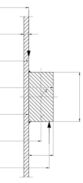
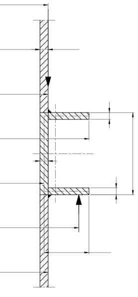
Standard and calculation basis: DIN EN 13445-3/16.13: 2018-12
Calculation workflow
- Enter the geometry of ring and shell: The dimensions of the support ring or ring girder (rectangular profile with width and height), its position on the cylindrical shell, and the diameter and wall thickness of the vessel in the attachment region are entered.
- Define the support arrangement: It is defined whether the ring rests on a continuous support or on several evenly distributed individual supports; in the second case, the number and arrangement of the supports determine the bending and torsional loading of the ring between the support points.
- Apply the loads: Governing are the weight of the vessel including contents and the global bending moment in the vessel at the height of the ring due to external loads (wind, earthquake, connected piping); from these, the vertical forces acting on the ring at each support follow.
- Verify the ring cross-section: For the ring, the internal forces and moments between and above the supports are determined, and the stresses in the profile are compared with the allowable values of the ring material at design temperature.
- Check the load introduction into the shell: Finally, the local loading of the vessel wall at the ring attachment is verified; if it is exceeded, a larger ring profile, more supports, or a greater shell wall thickness is required.
Input quantities
| Quantity | Symbol | Unit |
|---|---|---|
| Ring width | b | mm |
| Inside diameter of vessel | d1 | mm |
| Outside diameter of vessel | d2 | mm |
| Inside diameter of ring | d3 | mm |
| Outside diameter of ring | d4 | mm |
| Diameter to line load | d6 | mm |
| Diameter to supporting force | d7 | mm |
| Vessel wall thickness | e1 | mm |
| Thickness of ring | e3 | mm |
| Thickness of ring (internal ligament) | e4 | mm |
| Thickness of ring (external ligament) | e5 | mm |
| Allowable design stress of ring material | fT | N/mm² |
| Height of ring (see. Fig. 16.13-2) | h | mm |
| Number of local supports of the ring | ns | – |
| Weight of the vessel including vessel content | G | N |
| Global bending moment in vessel resulting from external loads at height of ring | M | N·mm |
| Safety factor | S | - |
| Safety factor | Stest | - |
| Nominal design strength | K | N/mm² |
| Nominal design strength | Ktest | N/mm² |
| Design pressure | P | MPa(p) |
| Temperature | T | °C |
| Load case | Lastfall | – |
| Supports distributed evenly | verteilt | – |
Calculated results
| Quantity | Symbol | Unit |
|---|---|---|
| g)beta | 16.13.4 g)β | – |
| g)delta | 16.13.4 g)δ | – |
| c)h | 16.13.4 c)b | – |
| c)b | 16.13.4 c)h | – |
| Supports evenly distributed | 16.13.4 e) | – |
| Einzelstütze | 16.13.5.1 | – |
| Rings | 16.13.5.1 | – |
| Equivalent supporting force Eq. (16.13-1) | F | N |
| Total equivalent force Eq. (16.13-2) | F | N |
| Allowable torsional moment Eq. (16.13-4) | Mt,max | N·mm |
| Allowable bending moment Eq. (16.13-5) | Mb,max | N·mm |
| Allowable shear force Eq. (16.13-6) | Qmax | N |
| Coefficient | Z0 | - |
| Coefficient | Z1 | - |
| Allowable supporting force Eq. (16.13-7) | FS,max | N |
| Allowable total load Eq. (16.13-8) | FS,max | N |
| Allowable unit bending moment (see Table 16.13-1) | mb | - |
| Allowable unit torsional moment (see Table 16.13-1) | mt | - |
| Allowable unit transverse force (see Table 16.13-2) | qt | - |
Calculation options
Supports distributed evenly
No · Yes
Design type
Design type I · Design type II
Profile selection
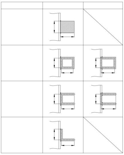
Rectangular solid section · Box section type I · Box section type II · U section type I · U section type II · L section
Position of profile
External · Internal
Frequently asked questions
When do you choose a ring support instead of a support skirt or support brackets?
A ring support is the natural choice when the vessel is suspended in a platform or supporting structure and the load is to be transferred at several points around the circumference. Compared with individual support brackets, the ring distributes the load introduction evenly around the circumference and reduces local stress peaks in the shell; compared with a support skirt, it saves headroom below the vessel bottom.
Why does the number of supports play such a large role?
Between the support points, the ring acts as a curved beam under bending and torsion; the internal forces grow markedly with the support spacing. More evenly distributed supports reduce the ring loading considerably but increase the structural effort. Non-uniform support arrangements are not covered by the standard method.
How does the global bending moment from wind or earthquake enter the verification?
The moment at ring height produces a non-uniform vertical force distribution around the circumference: on the leeward side it increases the support forces, on the windward side it relieves them, potentially up to uplift forces. The verification must cover the most unfavorable support force from the superposition of weight and moment, and where applicable also the anchorage against uplift.