Engineering task and calculation objective
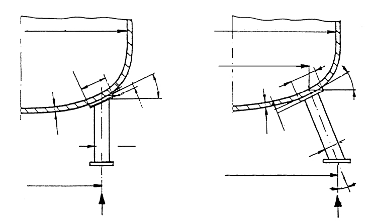
Module EN16.11 calculates vertical vessels on support legs to DIN EN 13445-3, clause 16.11. Verified is the local load introduction of the support legs into the dished end — for torispherical and semi-ellipsoidal ends, with or without a reinforcing plate under the leg. Additional external forces and moments on the vessel (from piping connections or attachments, for example) enter the leg forces.
To calculate support legs to EN 13445-3 means: from the dead weight, the global axial force and the global bending moment, the maximum force on the individual support leg is determined per Eq. 16.11-1 and compared with the allowable force, which depends on the local load-bearing capacity of the dished end at the introduction point. The governing parameters are the effective leg diameter, the position of the leg on the end, the analysis wall thickness, and the diameter and thickness of any reinforcing plate.
In practice this verification is needed for storage vessels, agitated vessels and small to medium-sized process apparatus that stand on three or four legs instead of a support skirt. In parallel, the module checks the allowable pressure of the spherical crown or spherical section per EN 13445-3, clause 7.
Standard and calculation basis: DIN EN 13445-3/16.11: 2018-12
Calculation workflow
- Define load case and material data: For the selected load case (operation, test, installation), the design pressure, design temperature and material are specified; from these follow the nominal design stresses with the corresponding safety factors, supplemented by the corrosion allowance and the wall thickness undertolerance.
- Enter end geometry: The type of dished end (torispherical or semi-ellipsoidal), outside or inside diameter, inside height and nominal wall thickness are entered; from these the module forms the analysis wall thickness, the mean diameter and the governing geometry ratios.
- Determine leg forces from global loads: From the weight, the global axial force and the global bending moment of the external loads, the maximum force on the most unfavourable support leg is calculated per Eq. 16.11-1 — the moment increases the force on the leeward side of the leg circle.
- Determine the allowable leg force: Via the effective diameter of the support leg, the equivalent calculation diameter and the geometric coefficient, the allowable force at the introduction point is determined — with a reinforcing plate, its diameter and thickness enter in addition.
- Combine the verifications: The actual leg force is compared with the allowable one; in parallel, the allowable internal pressure of the spherical crown/section is checked per EN 13445-3 clause 7, so that pressure capacity and local load introduction are covered together.
Input quantities
| Quantity | Symbol | Unit |
|---|---|---|
| Calculation temperature | t | °C |
| Calculation pressure | P | MPa |
| Material | Bodens | – |
| Thickness allowance | c1 | mm |
| Corrosion allowance | c2 | mm |
| Strength at t = | Betrieb | N/mm² |
| Strength at 20°C | Prüfung | N/mm² |
| Safety factor operation | Betrieb | – |
| Safety factor testing | Prüfung | – |
| Nominal design stress operation | Bodens | N/mm² |
| Nominal design stress testing | Bodens | N/mm² |
| Type of dished end | Bodens | – |
| Nominal design stress bolting up | Bodens | N/mm² |
| Internal diameter of dished end | Di | mm |
| Internal height of dished end | Hi | mm |
| Number of legs | n | - |
| Leg circle diameter | d1 | mm |
| Leg outside diameter | d2 | mm |
| Diameter of plate | d3 | mm |
| Diameter at junction of legs with head | d4 | mm |
| Nominal wall thickness of dished end | en | mm |
| Analysis wall thickness | en - c1 - c2 ea | mm |
| Thickness of plate | e2 | mm |
| Outside diameter of dished end | De | mm |
Calculation options
Type of dished end
Torispherical head (Kloepper type) · Torispherical head (Korbbogen type) · Hemispherical head · Semi-ellipsoidal head
Frequently asked questions
When is a reinforcing plate under the support leg required?
When the local load-bearing capacity of the end at the introduction point is smaller than the actual leg force. The reinforcing plate enlarges the effective introduction area and the equivalent calculation diameter, which increases the allowable force. Alternatives are more legs, a larger leg diameter or a thicker end wall.
How do external forces and moments enter the leg loading?
A global axial force is shared equally among all legs, while a global bending moment (e.g. from wind, piping loads or eccentric attachments) increases the force on the legs facing away from the moment. Eq. 16.11-1 combines both contributions into the maximum individual leg force; the number of legs and the pitch circle diameter of the legs determine the moment contribution.
Why is the position of the leg on the dished end limited?
The formulas of clause 16.11 apply to load introduction into the crown-near region of the end, where the shell curvature is defined. Legs too close to the knuckle or the straight flange lie outside the range of validity, because discontinuity stresses from knuckle bending would superimpose on the local load introduction there — in that case a different support arrangement or an individual analysis is required.
Does the verification also cover buckling of the support legs themselves?
No. Clause 16.11 verifies the local loading of the vessel wall at the introduction point. The legs themselves (column buckling, welds, base plates, anchoring) must additionally be designed to the applicable structural steel rules.