Engineering task and calculation objective
The KAP8 module calculates openings and branches in cylindrical shells to Chapter 8 of DIN EN 12953-3:2016, the design code for the pressure parts of shell boilers. Every nozzle, manhole and other opening interrupts the load-bearing cross-section of the internally pressurized boiler shell; the lost load-bearing capacity must be compensated by contributing wall regions, reinforced nozzles or reinforcing pads.
The verification follows the pressure-area method commonly used in the European boiler codes: the pressure-loaded area is compared with the stress-bearing cross-sectional area of shell, nozzle and reinforcement, each limited to the contributing lengths on either side of the opening. This makes it possible to calculate whether a nozzle in a boiler shell is permissible without reinforcement, or how much reinforcement cross-section is missing.
The module is needed for every new design and for modifications to existing boilers, for example when an additional branch is to be cut into an existing shell: it provides the complete opening verification to DIN EN 12953-3, including the check of adjacent openings for mutual interaction.
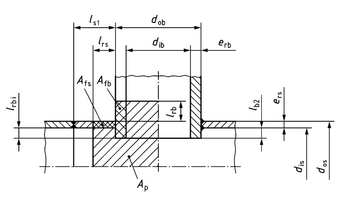
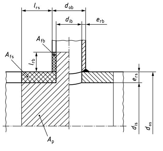
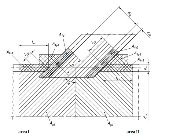
Calculation workflow
- Record shell data: First the diameter and as-built wall thickness of the cylindrical shell as well as the design pressure and design temperature are entered. The allowable design stress follows from the shell material; wall thickness in excess of the required basic wall thickness is available as reinforcement.
- Define opening and branch: The opening is described by diameter, location and design: unreinforced opening, set-through or set-on nozzle with wall thickness and protruding lengths, or a reinforcing pad with width and thickness. If nozzle and pad are made of different materials, their lower allowable stress is taken into account.
- Determine contributing lengths: The standard limits the regions of shell and nozzle that may be used to compensate the opening via contributing lengths that follow from diameter and wall thickness. Only the material within these limits counts as load-bearing cross-section.
- Evaluate the pressure-area comparison: The verification compares the pressure-loaded area with the stress-bearing cross-sectional areas of shell, nozzle and reinforcement. If the condition is not satisfied, the missing reinforcement cross-section is reported and the design is adapted, for example with a thicker nozzle or a reinforcing pad.
- Check adjacent openings and limits: If several openings lie close together, it is checked whether their disturbed zones overlap; in that case, the ligament between the openings must be verified separately. Finally, the geometric limits of application of the chapter are checked, such as permissible branch-to-shell diameter ratios.
Input quantities
| Quantity | Symbol | Unit |
|---|---|---|
| Load Case | Case | – |
| Subjected to heat transfer | transfer | – |
| Gas entery temperature | tG | – |
| Nominal shell thickness | e | mm |
| Heating by | by | – |
| Calculation pressure | pc | MPa(p) |
| Saturation temperature | ts | °C |
| Additional temperature | tz | °C |
| Calculation temperature | tc | °C |
| Type of Reinforcement | Reinforcement | – |
| Number of Nozzle | Nozzle | – |
| Branch inclination | inclination | – |
| Branch inclination | inclination | – |
| Cut method | method | – |
| With additional Reinforcement | Reinforcement | – |
| Reinforcement for nozzle | nozzle | – |
| Methods of Reinforcement | Reinforcement | – |
| Type of Nozzle 1 | 1 | – |
| Full welded | welded | – |
| Type of Nozzle 2 | 2 | – |
| Full welded | welded | – |
| Shell | Shell | – |
| Material Strength | Ks | N/mm² |
| Material strength shell | Rp0.2 | N/mm² |
Calculation options
Load Case
operation · test
Subjected to heat transfer
Yes · NO
Gas entery temperature
≤ 400 · 400-800 · > 800
Heating by
radiation · convection
Type of Reinforcement
Block Flange · Nozzle
Number of Nozzle
one · two
Branch inclination
radial · non radial · oblique
Branch inclination
radial · non radial
Frequently asked questions
When is an opening in a boiler shell permissible without reinforcement?
If the existing shell wall thickness is significantly greater than the calculated required thickness, the excess wall thickness within the contributing length can compensate small openings on its own. Whether this is sufficient is shown by the pressure-area comparison; fixed limit diameters without verification exist only for very small openings. The larger the opening and the tighter the shell design, the sooner a reinforced nozzle or a pad is needed.
What is the difference between reinforcement by nozzle and by reinforcing pad?
A thick-walled, welded-in nozzle acts with its cross-section within the contributing length directly at the disturbance and is thermally robust. A welded-on pad reinforces only the outside of the shell; it is simple to fabricate but less favorable under severe temperature transients and with respect to crevice corrosion. The standard also limits the creditable width and thickness of the pad.
How are two closely spaced nozzles treated?
If the distance between two openings is less than the sum of their disturbed zones, they may no longer be calculated as isolated openings. The ligament between the openings then governs: a combined pressure-area comparison is carried out for it in the most unfavorable section direction, taking into account the orientation of the ligament relative to the shell axis, because the circumferential stress is twice as large as the longitudinal stress.
Does Chapter 8 also apply to openings in end plates?
No. Chapter 8 of DIN EN 12953-3 deals with openings and branches in the cylindrical shell. Openings in dished ends are verified according to the end rules, and isolated openings in flat boiler end plates according to Chapter 11 of the standard.