Engineering task and calculation objective
The opening reinforcement per UG-37 answers only the question of whether enough cross-sectional area is available around a nozzle — not how the parts must be welded together. That is governed by ASME BPVC Section VIII Division 1, UW-16: the paragraph specifies permissible attachment weld details at openings and defines minimum dimensions for fillet and groove welds. This module checks the selected weld detail against exactly these requirements.
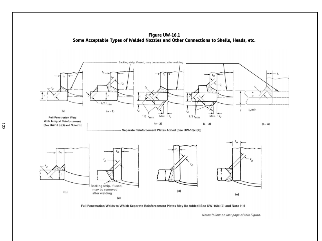
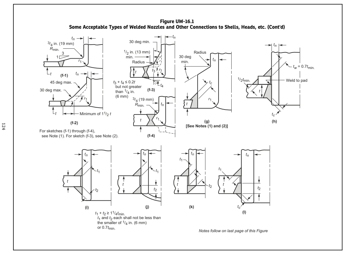
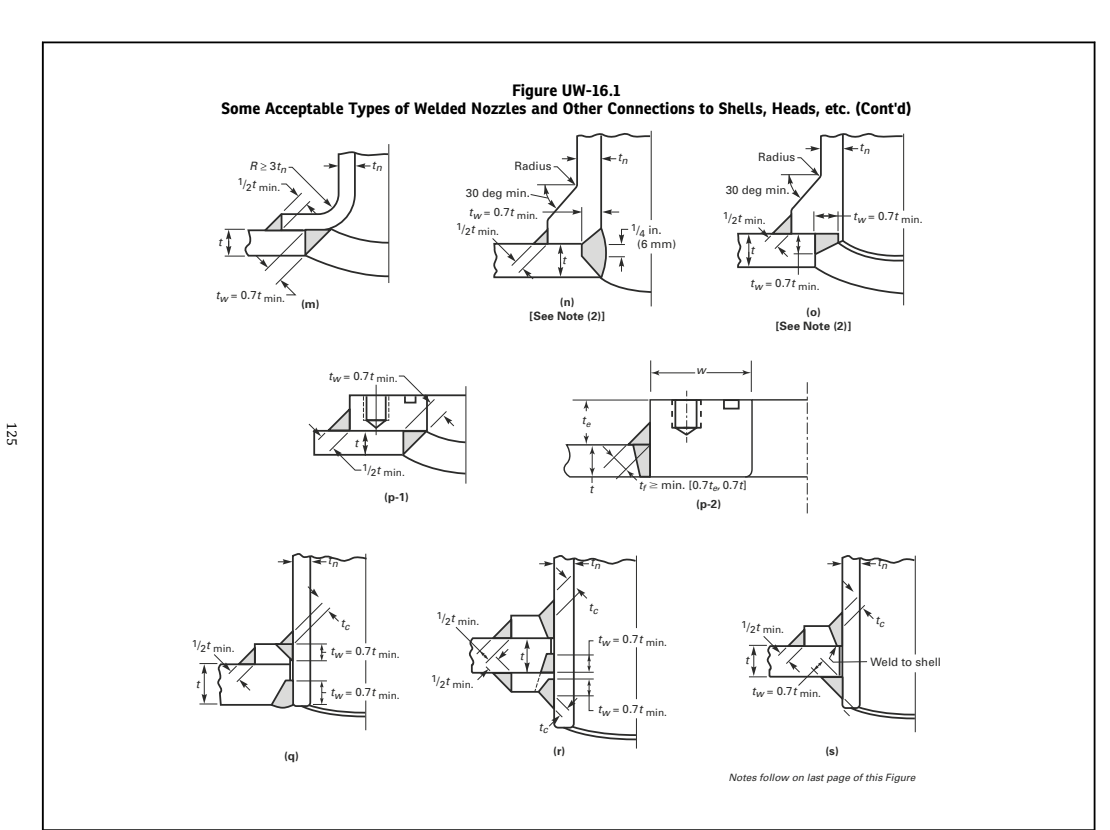
The weld detail is chosen graphically from the sketches of Figure UW-16.1 — from the inserted nozzle with fillet welds on both sides, through set-on nozzles, to details with a reinforcing pad. The module then checks the fillet weld throat dimension tc, the weld sizes t1 and t2 together with their minimum sum, the fillet weld size tw and the reinforcing-pad edge welds against the UW-16 limits (tmin, 0.7·tmin, 1.25·tmin).
If you need to calculate or check nozzle attachment welds to ASME VIII-1, UW-16 applies to every nozzle and connection design: in detail engineering, in inspection planning, and in evaluating fabrication deviations when an as-built fillet size is questioned.
Standard and calculation basis: ASME BPVC Sec. VIII Div. 1, UW-16 & Figure UW-16.1: 2025
Calculation workflow
- Select the weld detail per Figure UW-16.1: From the sketches of Figure UW-16.1 embedded in the mask, the design detail intended in the construction is chosen: inserted or set-on, full penetration or partial penetration, with or without a reinforcing pad. Each sketch has its own requirements for the weld dimensions to be verified.
- Determine the governing wall thicknesses: From the thicknesses of the parts to be joined (shell, nozzle, reinforcing pad), t_min is formed as the smaller of 19 mm (3/4 in.) and the thickness of the thinner part. t_min is the reference quantity for almost all UW-16 minimum weld dimensions.
- Determine the minimum weld dimensions: Depending on the detail, UW-16 requires: the fillet weld throat thickness tc at least the smaller of 6 mm and 0.7·t_min; for combined welds, the individual dimensions t1 and t2 with their minimum sum (typically 1.25·t_min); for reinforcing-pad edge welds, the fillet size tw as a function of pad and base material thickness.
- Check the as-built weld dimensions: The actually intended or fabricated weld dimensions (leg length, penetration depth) are converted into throat thicknesses — for equal-leg fillet welds, tc = 0.7·leg size — and compared against the minimum values.
- Document the result: For each weld, the module reports the required and the existing dimension. Unmet requirements immediately show which weld must be enlarged or which alternative detail per Figure UW-16.1 must be selected. The strength verification of the weld load paths (per UG-41/UW-15) is a separate step.
Input quantities
| Quantity | Symbol | Unit |
|---|---|---|
| Shell/head thickness t | – | – |
| Nozzle wall thickness tn | – | – |
| Corrosion allowance c | – | – |
| Reinforcing plate te | – | – |
| Material | – | – |
| Execution | – | – |
| actual throat tc | – | – |
| actual weld outside t1 | – | – |
| actual weld inside t2 | – | – |
| actual fillet size tw | – | – |
| actual throat outer edge | – | – |
| actual throat inner edge | – | – |
| Nominal size NPS | – | – |
| t_min | – | – |
| required tc | – | – |
| required each side | – | – |
| required sum t1+t2 | – | – |
| required tw | – | – |
| required outer edge | – | – |
| required one-side | – | – |
| Check tc | – | – |
| Check t1,t2 | – | – |
| Check t1+t2 | – | – |
| Check tw | – | – |
Calculation options
Execution
1 · 2 · 3 · 4 · 5 · 6 · 7
Worked example
An inserted nozzle (detail per Figure UW-16.1 with fillet welds on both sides) is welded into a vessel shell. The required minimum size of the outer fillet weld per UW-16 is to be checked.
Given values
| Nozzle wall thickness tn | 8.8 mm |
| Shell wall thickness ts | 12.0 mm |
| Upper limit for tmin per UW-16 | 19 mm (3/4 in.) |
Solution
Governing thickness tmin
tmin = min(19 mm; tn; ts) = min(19; 8.8; 12.0) = 8.8 mm
Required fillet weld throat thickness tc
tc ≥ min(6 mm; 0.7·tmin) = min(6 mm; 0.7 · 8.8 mm) = min(6; 6.16) = 6.0 mm
Conversion into the leg size
For an equal-leg fillet weld, tc = 0.7 · leg size, hence:
Leg size ≥ 6.0 / 0.7 = 8.6 mm
A fillet weld with a 9 mm leg size is selected (tc = 0.7 · 9 = 6.3 mm ≥ 6.0 mm).
Result
| Governing thickness tmin | 8.8 mm |
| Required throat thickness tc | 6.0 mm |
| Selected fillet weld leg size | 9 mm |
All values are illustrative. The applicable standard and project-specific boundary conditions remain authoritative.
Frequently asked questions
Does UW-16 replace the weld load verification per UW-15/UG-41?
No, the two verifications stand side by side. UW-16 provides constructive minimum dimensions so that the joint has a robust basic strength independent of the calculated load. UW-15 in conjunction with UG-41 additionally requires that the weld load paths can carry the forces actually to be transferred from the opening reinforcement. For highly utilized reinforcements, the load path verification can demand larger welds than the UW-16 minima.
What is the difference between the leg size and the throat thickness tc?
The leg is the cathetus length of the fillet weld, tc is the throat thickness — for equal-leg fillet welds 0.707 times the leg size; UW-16 uses the simplified factor 0.7. Anyone who fabricates the required throat thickness tc directly as the leg size undercuts the requirement by about 30 % — a classic error source when transferring it into the welding procedure specification.
Why is there the upper limit of 19 mm for t_min?
The minimum weld dimensions are meant to prevent the attachment weld from tearing off under shrinkage, bending and start-up loads. Beyond a certain plate thickness, this need no longer grows in proportion to the wall thickness; UW-16 therefore caps the reference quantity at 19 mm (3/4 in.). Thicker components thus do not require arbitrarily large fillet welds — the load path verification then remains governing.
Do the UW-16 requirements also apply to reinforcing pads?
Yes. The edge welds of the reinforcing pad have their own minimum dimensions tw, depending on the pad thickness and t_min; in addition, the pad must be able to participate in the load paths through its welds. Furthermore, the code requires a telltale hole in the pad that must not be welded shut — it serves the leak-tightness check of the inner weld.