Engineering task and calculation objective
The A188 module calculates fixed tubesheets of shell-and-tube heat exchangers to ASME BPVC Section VIII, Division 2, paragraph 4.18. In the fixed-tubesheet design both tubesheets are rigidly welded to the shell — tubes and shell form a statically indeterminate system in which pressure and temperature loads interact. Anyone who wants to calculate a fixed-tubesheet heat exchanger to ASME cannot avoid this interaction analysis.
The core of the method is the stiffness assessment: the shell axial rigidity Ks (or Ks* with an expansion joint), the axial rigidity of the individual tubes Kt, and the resulting stiffness ratios such as Ks/(Nt·Kt) determine how the axial loads from tube-side and shell-side pressure and from restrained differential thermal expansion between tube bundle and shell are shared. An expansion joint is accounted for through the ratio Kj/(Ks+Kj) and relieves the system noticeably.
In practice this calculation is needed for every rigidly welded tube-bundle apparatus in plant engineering — evaporators, condensers, process coolers — especially where large temperature differences occur between the tube side and the shell side. The module delivers the tubesheet thickness, the tube and shell stresses, and the assessment of whether an expansion joint is required.
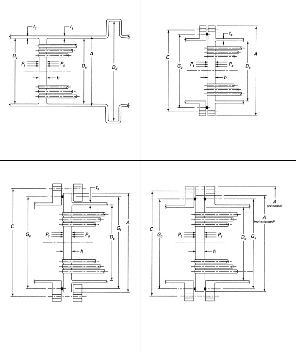
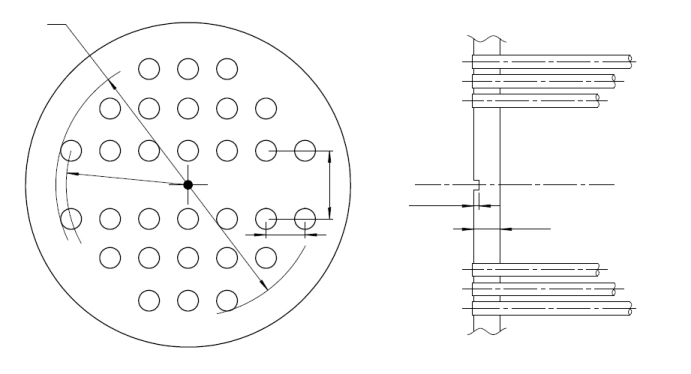
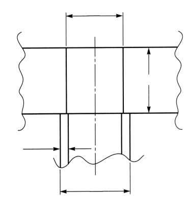
Standard and calculation basis: ASME BPVC VIII-2, A4188 2025
Calculation workflow
- Define geometry and configuration: First, the tubesheet diameter, tube pitch, tube dimensions, number of tubes N₁, and the configuration per 4.18 (attachment to shell and channel, gasketed or welded) are defined. From these, the effective characteristics of the perforated region such as ligament efficiency and effective modulus of elasticity are derived.
- Determine axial rigidities: The shell axial rigidity K₅ (K₅* with an expansion joint), the axial rigidity of one tube Kₜ, and — if present — the expansion joint rigidity Kⱼ are calculated from cross-sectional areas, moduli of elasticity, and lengths. The stiffness ratios K₅/(Nₜ·Kₜ) and Kⱼ/(K₅+Kⱼ) govern the load sharing in the system.
- Set up the load cases: Per 4.18.8, the governing load cases are combined from tube-side pressure, shell-side pressure, and the temperature difference between tube bundle and shell — each individually and superimposed, for the operating condition and, where applicable, the test condition.
- Verify the tubesheet stresses: For each load case the bending and shear stresses in the tubesheet are compared with the allowable values. Exceedances lead to a thicker plate or — for thermally dominated load cases — to an elastic-plastic reassessment in accordance with the code.
- Check tubes, shell, and joint: Finally, the axial tube stresses (tension and compression including a buckling check), the shell longitudinal stress in the attachment region, and the load capacity of the tube-to-tubesheet joint are verified. If the joint capacity is insufficient, an expansion joint or a revised geometry is required.
Input quantities
| Quantity | Symbol | Unit |
|---|---|---|
| Variable 1 | T= < | – |
| Tubesheet material | – | – |
| Thickness | < | – |
| Outside diameter | – | – |
| Strength | *) | – |
| Strength operat. | – | – |
| Safety factor | – | – |
| Safety operation | – | – |
| Modulus of elasticity | **) | – |
| Allowance | c1 | – |
| Corros. all. | c2 | – |
| Tubesheet flange thickness | hr | – |
| Thermal expansion | – | – |
| Load case (1=operation, 2+3=test at 20°C, 4=other) | – | – |
| Variable 17 | *) | – |
| Yield strength | – | – |
| Yield strength | – | – |
| Tensile strength | – | – |
| Allow. stress | *) | – |
| Prim.+sec. str. | *) | – |
| Yield strength of shell at Ts = | Sy1s | – |
| Shell material (Type abc) | – | – |
| Internal operating pressure shell side | Ps | – |
| Thickness | ts = : | – |
Calculated results
| Quantity | Symbol | Unit |
|---|---|---|
| Max. gasket seating force chan.=0.5(Am+Ab)·Ksp/Ssp, Table 4.16.2 | W | – |
| Channel inside diameter corroded (type a) | Dc | – |
| Channel shell thickness without allowances | tc | – |
| Shell thickness without allowances | ts | – |
| Stiffness ratio Kj/(Ks+Kj) | J | – |
| Shell inside diameter corroded (type abc) | Ds | – |
| Variable 248 | Tr Ts* Tc* | – |
| Variable 249 | Tr Ts* Tc* | – |
| Variable 250 | Tr Ts* Tc* | – |
| Variable 252 | Ps* Pc* Pω | – |
| Variable 253 | Ps* Pc* Pω | – |
| Variable 254 | Ps* Pc* Pω | – |
Frequently asked questions
When does a fixed-tubesheet heat exchanger require an expansion joint?
When the restrained differential expansion between tube bundle and shell produces inadmissible axial stresses in the tubes, the shell, or the tube-to-tubesheet joint. The 4.18 procedure shows this directly: if one of the checks in the thermal load cases fails, an expansion joint lowers the restraint forces significantly via the stiffness ratio Kⱼ/(K₅+Kⱼ), because the soft bellows absorbs most of the differential expansion.
How does the ASME method differ from the classical TEMA tubesheet calculation?
ASME VIII-2, 4.18 is based on the elastic analysis of the tubesheet-shell-channel interaction (Gardner/Soler model) and treats the tubesheet as a plate on an elastic foundation formed by the tube field. TEMA, by contrast, uses a simplified formula with lump-sum coefficients. The ASME method usually yields more realistic, often smaller tubesheet thicknesses, but demands considerably more input data and the evaluation of several load cases.
Why must load cases with only one acting pressure also be evaluated?
Because the system is statically indeterminate, the condition with only tube-side or only shell-side pressure (for example during start-up, shutdown, or the pressure test of one side) can produce higher stresses than the condition with both pressures acting simultaneously. The code therefore requires the evaluation of all pressure-temperature combinations, not just the nominal operating point.
What role does the tube-to-tubesheet joint play in the verification?
The maximum axial load per tube resulting from the interaction analysis must be transferred by the joint (expanded, welded, or combined). The allowable load of this joint is determined separately — for example per ASME VIII, Nonmandatory Appendix A — and compared with the calculated tube axial force. It is frequently the limiting element at high temperature differences.