Engineering task and calculation objective
The A4187 module calculates tubesheets of U-tube heat exchangers according to the rules of the ASME Boiler and Pressure Vessel Code, Section VIII, Division 2, paragraph 4.18 (Rules for the Design of U-Tube Tubesheets). In a U-tube exchanger, a single tubesheet carries the entire bundle; since the tubes are bent back freely, no constraint forces arise from differential thermal expansion between shell and tubes — the tubesheet is verified as a perforated plate under the tube-side and shell-side pressures.
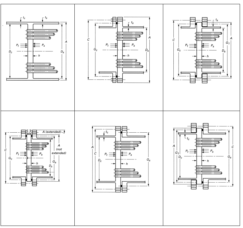
The ASME rules treat the tubesheet as an equivalent solid plate with effective elastic constants that capture the weakening by the hole field via the ligament efficiency. The verifications cover the bending stresses in the tubesheet and the shear stress at the edge of the perforated region for all governing load cases — tube-side pressure alone, shell-side pressure alone, and both acting together. Depending on the configuration, the module accounts for clamping of the tubesheet between shell and channel flanges, integral construction with shell or channel, and gasketed or bolted arrangements.
This calculation is needed for the design and rating of U-tube bundles to the ASME code — for example for export projects or equipment with an ASME stamp, where the tubesheet verification must be carried out not per European rules (EN 13445 or the German AD 2000 code) but per Section VIII.
Standard and calculation basis: ASME BPVC VIII-2, A4187 2025
Calculation workflow
- Define the tubesheet configuration: First, the installation arrangement is chosen: tubesheet integral with shell and/or channel, bolted between flanges, or gasketed. The configuration determines the boundary conditions of the plate calculation and which adjacent components (shell, channel, flange) participate.
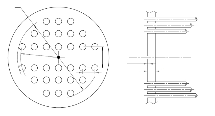
- Characterize the hole field: From the tube pitch, tube diameter, tube wall thickness and, where applicable, the expanded or welded tube-to-tubesheet joint, the effective ligament efficiency is determined; from it follow the effective elastic constants of the equivalent solid plate and the effective depth of the perforated zone.
- Set up the load cases: The verifications are carried out for the prescribed pressure combinations: tube-side design pressure alone, shell-side design pressure alone, and both pressures simultaneously — in each case taking test and operating conditions into account.
- Calculate the stresses in the tubesheet: Using the formulas of paragraph 4.18, the bending stress in the perforated region and the shear stress at the perimeter of the hole field are calculated; for integral configurations, the stresses in the adjoining shell and channel sections are determined as well.
- Acceptance check and iteration: The calculated stresses are compared with the allowable values of the ASME code. If a criterion is violated, the tubesheet thickness or the connection geometry is increased and the calculation repeated until all load cases are satisfied.
Input quantities
| Quantity | Symbol | Unit |
|---|---|---|
| Boden | T= < | °C |
| Material tubesheet | Boden | – |
| Thickness | < | mm |
| Outside diameter | Boden | mm |
| Strength | *) | MPa |
| Strength | Betrieb | MPa |
| Safety fac. | Prüfung | – |
| Safety fac. | Betrieb | – |
| Modulus of elasticity | **) | MPa |
| Modulus of elasticity | **) | MPa |
| Allow. c1 | Boden | mm |
| Corr.all. c2 | Boden | mm |
| Therm.exp. | Boden | 1E-6/°C |
| Load case (1=Operation, 2+3=Test at 20°C, 4=other) | 2+3=Prüfung) | – |
| Lastfallbezeichnung | *) | – |
| Yield str. | Boden | MPa |
| Yield str. | (Raumtemperatur) | MPa |
| Tensile str. | (Raumtemperatur) | MPa |
| or | *) | MPa |
| Pr.+sec.st | *) | MPa |
| Material shell (Type abc) | Mantel | – |
| Internal operating pressure shell side | Ps | MPa |
| Thickness | Manteldicke | mm |
| Outside diameter | Mantel | mm |
Calculated results
| Quantity | Symbol | Unit |
|---|---|---|
| or | *) | MPa |
| or | *) | MPa |
| Equivalent diameter of outer tube limit circle | D0 | mm |
| Effective tube pitch | p* | mm |
| Basic ligament efficiency for shear | μ | – |
| Effective ligament efficiency for bending | μ* | – |
| Tubesheet thickness without allowances > hin | h | mm |
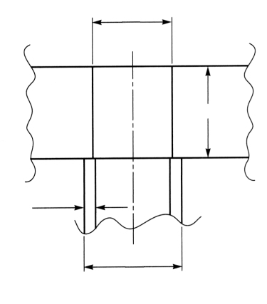
| Effective tube hole diameter | d* | mm |
| Effective tubeside pass partition groove depth | hg' | mm |
| Effective mod. elasticity tubesheet | E* | MPa |
| Effective Poisson's ratio of tubesheet | ν* | – |
| Inside diameter of channel, corroded (Type ade) | Dc | mm |
| Channel thickness without allowances | tc | mm |
| Shell thickness without allowances | ts | mm |
| Gasket seating force = 0.5(Am+Ab)·Ksp/Ssp | Table 4.16.2 Wm | N |
| Ratio Ds/D0 (Type abc) or Gs/D0 (Type def) | ρS | – |
| Ratio Dc/D0 (Type aef) or Gc/D0 (Type bcd) | ρC | – |
| Inside diameter of shell, corroded (Type abcd) | Ds | mm |
| Bedingungen | Bedingungen | – |
| Recommended initial tubesheet thickness | 4.18.3 hin | mm |
| Tubesheet rim moment due to Ps and Pt | MTS | N |
| Coefficient for shell pressure, Type abc | δS | mm^3/N |
| Coefficient for moment of shell | ωS | mm² |
| Coefficient for channel pressure, Type aef | δc | mm^3/N |
Calculation options
Configuration of the tubesheet
97 · 98 · 99 · 100 · 101 · 102
_Konfiguration
Tubesheet integral with shell and channel · Tubesheet with flange, integral with shell, gasketed with channel · Without flange, integral with shell, gasketed with channel · Tubesheet gasketed with shell and channel · Tubesheet with flange, gasketed with shell, integral with channel · Without flange, gasketed with shell, integral with channel
Frequently asked questions
Why is the tubesheet verification simpler for a U-tube exchanger than for a fixed tubesheet exchanger?
In a U-tube bundle, the tubes are attached to only one tubesheet and can expand freely. No axial constraint forces arise from the thermal expansion difference between shell and tubes, as they do in a fixed tubesheet exchanger, where they often make an expansion joint necessary. The tubesheet is therefore loaded only by the pressures of both sides; the tubes do not act as an elastic foundation as they do in the fixed tubesheet calculation per 4.18.8.
What does the ligament efficiency mean, and why is it so important?
The ligament is the remaining web of material between two adjacent tube holes. The effective ligament efficiency μ* relates this web to the tube pitch and also captures the stiffening effect of expanded or welded tube ends. It determines the effective elastic constants of the equivalent solid plate — a smaller ligament means a more flexible, more highly stressed plate and thus greater required tubesheet thicknesses.
Do all pressure load cases really have to be calculated, even when one case appears obviously governing?
Yes. Which combination governs depends on the configuration: for tubesheets bolted between flanges, the flange moments can be decisive; for integral constructions, the junction stresses in shell or channel. Moreover, a pressure acting on the shell side only or the tube side only (e.g. during the pressure test of one side) produces different bending directions than the combined loading — that is why the code prescribes the separate investigation of all combinations.
Can the ASME verification be replaced by a calculation per EN 13445 or AD 2000?
Not readily. Although EN 13445-3 clause 13 and the German AD 2000 code cover the same component type, the safety concepts, allowable stresses and detailed formulas differ. For equipment with an ASME stamp or in projects with an ASME contractual basis, the verification must be carried out per Section VIII; the module implements the rules of Division 2, paragraph 4.18, for this purpose.