Engineering task and calculation objective
The A189 module calculates floating tubesheets of shell-and-tube heat exchangers to ASME BPVC Section VIII, Division 2, paragraph 4.18. In the floating-head design only one tubesheet is fixed to shell and channel, while the second tubesheet with the floating head remains free to move axially. The thermal expansion of the tube bundle is thereby accommodated largely without restraint — a decisive advantage at large temperature differences between the tube side and the shell side.
The module calculates the stationary and the floating tubesheet for the governing pressure load cases, along with the adjacent components: among other results it reports the required channel thickness and shell thickness without allowances and, for flanged configurations, takes the bolt loads into account, including the gasket seating force per Appendix 2-5, which acts as an edge moment on the tubesheet.
This calculation is needed in pressure vessel and heat exchanger fabrication wherever tube bundles must be pulled and mechanically cleaned, or where fixed-tubesheet designs are ruled out by differential expansion — typically for process heat exchangers in refineries and chemical plants of TEMA types P, S, T, or W.
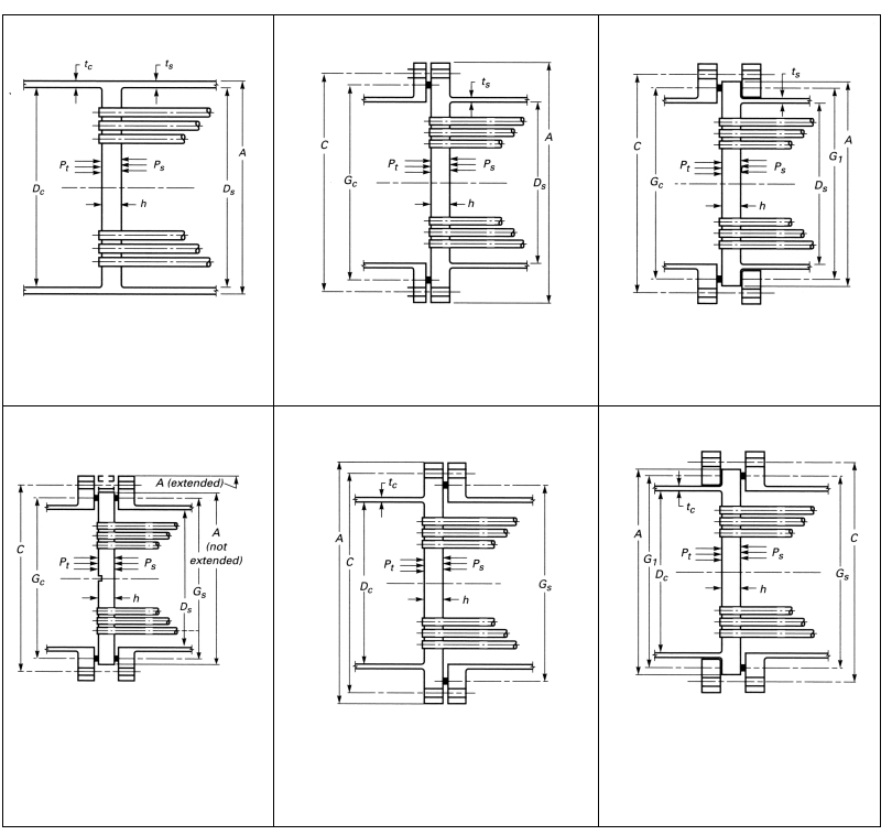
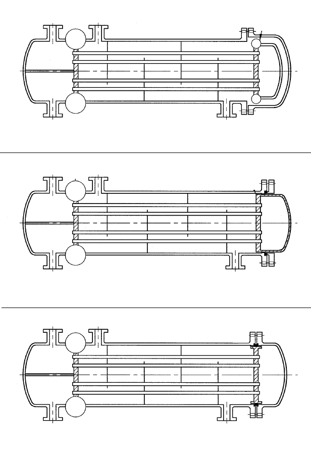

Standard and calculation basis: ASME BPVC VIII-2, A4189 2025
Calculation workflow
- Select design type and configuration: First, the floating-head configuration per 4.18 is selected (e.g., internal floating head with backing ring or externally sealed floating head). It determines the boundary conditions of both tubesheets and which components — channel, shell, flanges — enter the calculation.
- Capture the tube field geometry: Tubesheet diameter, tube pitch, tube dimensions, and number of tubes yield the ligament efficiency and the effective elastic characteristics of the perforated plate with which both tubesheets are treated as equivalent solid plates.
- Set up the pressure load cases: Tube-side and shell-side pressure are applied individually and together. Unlike the fixed-tubesheet design, thermal restraint load cases are largely eliminated because the floating head releases the differential expansion — the pressure load cases, however, must still be verified for both tubesheets.
- Apply edge loads from flange and gasket: For flanged tubesheets, the bolt forces and the gasket seating force 0.5·(Aₘ+Aᵇ)·Kₛₚ/Sₛₚ per Appendix 2-5 enter as edge moments. They can significantly increase the bending stress in the tubesheet, particularly in the gasket seating condition.
- Perform the verifications: For each load case, the bending and shear stresses of both tubesheets, the axial tube stresses including the buckling check, and the required wall thicknesses of channel and shell in the attachment region are compared with the allowable values. If exceeded, the tubesheet thickness is adjusted iteratively.
Input quantities
| Quantity | Symbol | Unit |
|---|---|---|
| Variable 1 | T= < | – |
| Tubesheet material | – | – |
| Thickness | < | – |
| Outsidediameter | – | – |
| Strength | *) | – |
| Strength | – | – |
| Safety | – | – |
| Safety | – | – |
| Modulus of elasticity | **) | – |
| Allow. c1 | – | – |
| Corr.all.c2 | – | – |
| Figure | – | – |
| Therm.dil. | – | – |
| Load case (1=operation, 2+3=test at 20°C, 4=other) | – | – |
| Variable 17 | *) | – |
| Yield str. | – | – |
| Yield str. | – | – |
| Tensile str. | – | – |
| All.stress | *) | – |
| case 4-7 | *) | – |
| Shell material (Type abc) | – | – |
| Shell side internal operating pressure | Ps | – |
| Thickness | – | – |
| Outsidediameter | – | – |
Calculated results
| Quantity | Symbol | Unit |
|---|---|---|
| Channel thickness without allowances | tc | – |
| Shell thickness without allowances | ts | – |
| Gasket seating force = 0.5(Am+Ab)·Ksp/Ssp, App.2-5 | W | – |
Frequently asked questions
When is a floating head chosen instead of a fixed tubesheet?
When the temperature difference between tube bundle and shell is so large that a fixed-tubesheet design would produce inadmissible restraint stresses, or when the bundle must be pulled for cleaning. The floating head decouples the axial expansion, but at the cost of a more complex construction, an additional internal sealing point, and slightly lower tube field utilization.
Do thermal load cases still have to be considered with a floating head?
The axial differential expansion is released by the movable tubesheet, so the restraint load cases typical of fixed tubesheets are eliminated. Radial temperature gradients within the tubesheet itself and different operating conditions (only one side pressurized, start-up, pressure test) must, however, still be verified as separate load cases.
Why does the gasket seating force per Appendix 2-5 appear in the tubesheet calculation?
For a flanged tubesheet, the bolt force acts not only on the flange ring but also produces an edge moment on the plate via the lever arm to the gasket. In the gasket seating condition the bolt force 0.5·(Aₘ+Aᵇ)·Sᵇ governs; it can stress the plate in bending more severely than the operating pressure and must therefore not be neglected.
What limits the permissible operating range of the externally sealed floating head?
In externally sealed designs (TEMA W), only a packing separates the tube side and shell side from the atmosphere. Codes and operator specifications usually restrict such constructions to moderate pressures and non-critical media, because a packing failure leads directly to external leakage. For higher requirements, internal floating heads with a bolted cover should be used.