Engineering task and calculation objective
The APA module determines the allowable axial loads of the tube-to-tubesheet joint to ASME BPVC Section VIII, Division 1, Nonmandatory Appendix A. The tube-to-tubesheet joint — expanded, welded, or combined — must transfer the axial tube forces that arise in fixed-tubesheet heat exchangers from the pressure and temperature load cases. For this, Appendix A defines the maximum allowable axial load per tube in both directions (push-out and pull-out).
The allowable load results from the tube cross-sectional area, the allowable stress of the tube material, and the joint efficiency fr: for standardized joint types, Table A-2 provides tabulated factors without testing; alternatively, fr is determined from pull-out or push-out tests per A-4 — with a safety factor applied to the lowest failure load and conversion from room to operating temperature via the tensile strength ratio of the tube material. For purely expanded joints, the expanded length (via the factor fe) and the difference in yield strengths of tube and tubesheet material (factor fy) additionally enter, as does the interface pressure remaining between tube and tubesheet after fabrication and in service.
This calculation is needed for every shell-and-tube heat exchanger to ASME whose tubesheet calculation (e.g., per VIII-1 Part UHX or VIII-2, 4.18) delivers axial forces per tube: the verification that the joint carries these forces is frequently the limiting element at large temperature differences.
Standard and calculation basis: ASME BPVC VIII Nonmandatory Appendix A, Edition 2019
Calculation workflow
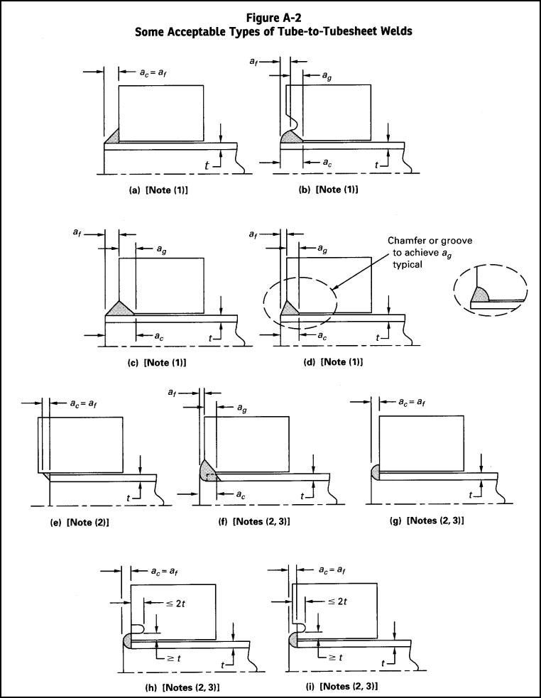
- Classify the joint type: First, the joint type is defined: expanded only (with or without grooves), welded only (seal weld or strength weld), or combined. The type determines which joint efficiency fr from Table A-2 applies and whether qualification by tests per A-4 is required or advantageous.
- Capture geometry and material data: Inputs are the tube outside diameter, nominal wall thickness and from these the tube cross-sectional area, the length of the expanded portion of the tube, and the materials of tube and tubesheet with allowable stress, yield strengths at design temperature, and tensile strengths at room and operating temperature.
- Determine the joint efficiency: Without tests, fr(no test) is taken directly from Table A-2. With tests, an fr(test) is calculated from the lowest failure load of the specimen series — at operating temperature or on heat-soaked specimens at room temperature — applying the safety factor and the tensile strength ratio operating/room temperature; the applicable or smaller value governs.
- Apply the correction factors for expanded joints: For expanded joints, the factor fe for short expanded lengths and the factor fy for the case that the yield strength of the tubesheet lies below that of the tube reduce the transferable load. The interface pressure remaining after expansion and its relaxation in service due to differential thermal expansion are also assessed.
- Calculate the allowable axial load and compare: The maximum allowable axial load Lmax of the joint results from the tube cross-sectional area, the allowable tube stress, and the factors fr, fe, and fy. It is compared with the largest occurring tube axial force from the tubesheet calculation for all operating conditions; if exceeded, a strength weld, grooves, or a longer expanded length must be provided.
Input quantities
| Quantity | Symbol | Unit |
|---|---|---|
| Tube cross-sectional area | At | m² |
| Allowable stress for tube material | Sa | N/mm² |
| Tube joint efficiency, which is set equal to the value of fr(test) or fr(no test) | fr | - |
| Factor for the length of the expanded portion of the tube | fe | - |
| Factor for difference in the mechanical properties of tubesheet and tube materials | fy | - |
| Factor for tube joint strength | fT | - |
| Interface pressure between the tube and tubesheet that remains after expanding the tube at fabrication | P0 | MPa(p) |
| Interface pressure between the tube and tubesheet due to differential thermal growth | Pt | MPa(p) |
| Maximum allowable stress value as given in the applicable part of section II, Part D | S | N/mm² |
| Yield strength for tubesheet material at T | Sy | N/mm² |
| Yield strength for tube material at T | Sy,t | N/mm² |
| Tubesheet design temperature | T | °C |
| Safety factor | k | - |
| Type of tube joint | joint | – |
| Maximum allowable axial load in either direction on tube-to-tubesheet joint | Lmax | N |
| Nominal tube outside diameter | d0 | mm |
| Nominal tube wall thickness | t | mm |
| Expanded tube joint with enhancements? | enhancements? | – |
| Length of expanded portion of the tube | l | mm |
| Load case | conditions? | – |
| Tube joint efficiency calculated from results from tests in accordance with A-4 taken from table A-2 for tube joints qualified by tests, whichever is less, except as permitted in A-3 (k) | fr(test) | - |
| Tube joint efficiency taken from Table A-2 for tube joints not qualified by test | fr(notest) | - |
| Lowest axial load at which failure occurs at operating temperature | L1(test) | N |
| Lowest axial load at which failure of heat soaked specimen tested at room temperature occurs | L2(test) | N |
Calculated results
| Quantity | Symbol | Unit |
|---|---|---|
| Operating condition A-5 (6) | (6) | – |
| Operating condition A-5 (7) | (7) | – |
Calculation options
Type of tube joint
1 · 2 · 3 · 4 · 5 · 6 · 7 · 8 · 9 · 10 · 11 · 12
Expanded tube joint with enhancements?
No · Yes
Type of axial forces
Pressure-induced · Thermally or pressure plus thermally induced (weld throat thickness less than tube wall thickness t) · Thermally or pressure plus thermally induced (all others)
Frequently asked questions
When is qualification of the joint by tests per A-4 worthwhile?
The tabulated fr values without testing are deliberately conservative — for expanded-only joints without grooves, in some cases very low. Pull-out or push-out tests on representative specimens permit considerably higher factors and thus leaner constructions. They pay off in series production, at high axial forces, or when the tabulated values narrowly fail the verification. The specimens must reproduce the fabrication process, materials, and hole geometry of the real joint.
Why does a purely expanded joint lose load capacity at high temperature?
The expanded joint carries load through friction from the interface pressure, which is created as an elastic-plastic preload during expansion. If the tube expands more than the tubesheet in service (or the material relaxes), this interface pressure decays — Appendix A captures this via the interface pressure from differential thermal expansion and via heat-soak tests. For larger temperature differences or cyclic operation, an additional weld is therefore the more robust solution.
What distinguishes a seal weld from a strength weld at the tubesheet?
The seal weld is intended only to prevent leakage between the tube side and shell side; its load capacity is not credited — the axial load is carried by the expanded joint. The strength weld is sized with a defined throat thickness for the full axial load and accordingly receives high fr values. The classification decides the weld geometry, the extent of examination, and the joint efficiency to be applied.
Is Appendix A binding — and how does it relate to UHX?
Appendix A is nonmandatory but is used in practically every case where the tubesheet rules (UHX or VIII-2, 4.18) require a verification of the tube-to-tubesheet joint against the calculated axial forces. It delivers the allowable load of the joint; the occurring load comes from the tubesheet calculation. Contractually, the customer may additionally demand stricter rules (e.g., HEI, customer-specific specifications).