Engineering task and calculation objective
The W-CAD module generates a scale drawing of the shell and tube heat exchanger from the calculation data of the WTS heat exchanger design module and stores it as a DXF file. The drawing follows the TEMA type designation of the apparatus (front head, shell, rear head) and shows the shell, tube bundle, tubesheets, inlet and outlet nozzles and the flange connections true to dimension.
Built-in DIN flange catalogs ensure that the flange connection nominal widths, pressure ratings and flange types of the nozzles are drawn with their actual catalog dimensions — the representation is therefore not merely schematic but dimensionally reliable. Operating data such as inlet and outlet temperatures, inlet pressures, design temperature and design pressure of both sides accompany the geometry and document the design condition of the apparatus.
In practice, W-CAD closes the gap between thermal design and mechanical engineering: the DXF output can be imported directly into CAD systems and used there for plot plan work, inquiry drawings, or as the basis for the fabrication drawing — without the main dimensions having to be transferred manually from the calculation report.
Calculation workflow
- Take over the calculation data from WTS: The geometric and thermal results of the heat exchanger design — inside diameter, tube bundle data, temperatures and pressures of both sides — are transferred from the WTS module into the drawing module.
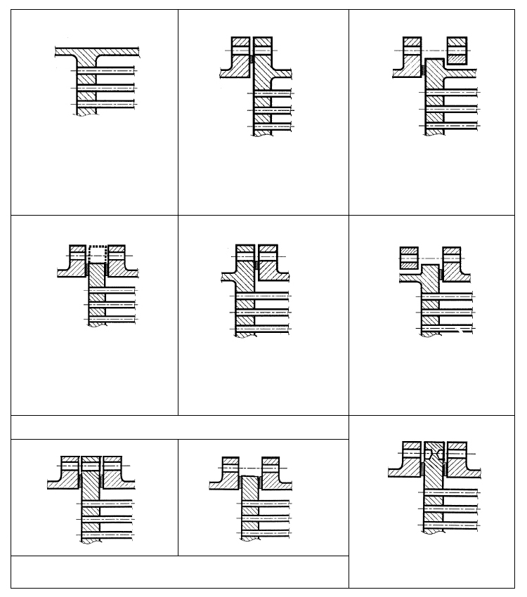
- Define the construction via the TEMA type: The three-letter TEMA designation for front head, shell and rear head (e.g. BEM, BEU, AES) determines the construction shown: fixed tubesheet, U-tube bundle or floating head with the associated head and cover variants.
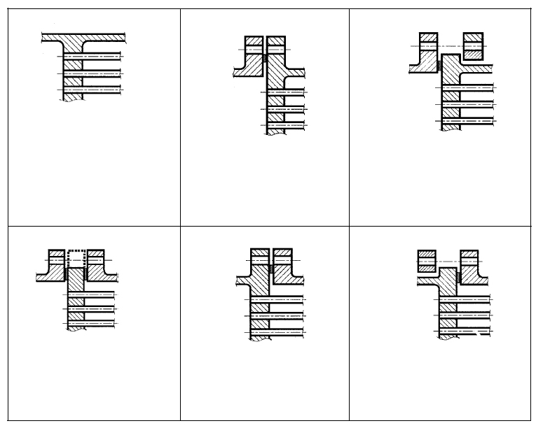
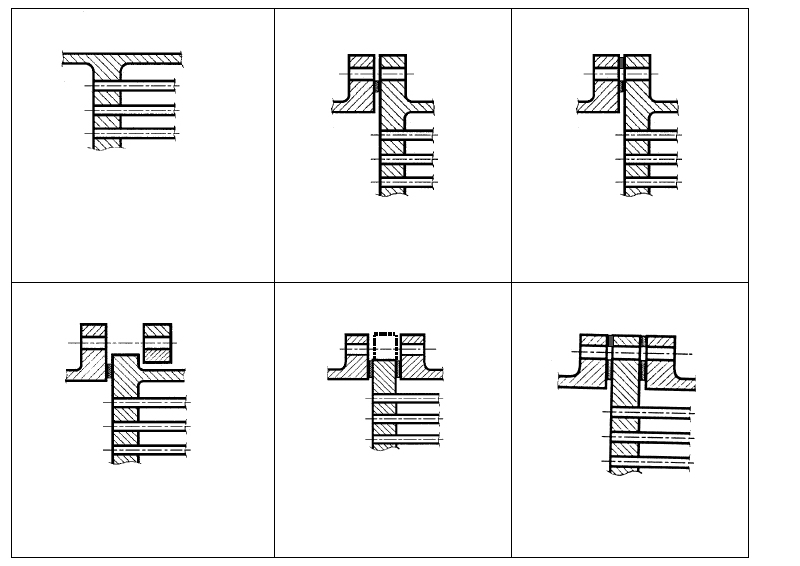
- Assign nozzles and flanges: For the inlet and outlet nozzles of both sides, the flange connection nominal width, pressure rating and flange type are selected; the dimensions are taken from the built-in DIN flange catalogs, while nozzle wall thickness and outside diameter complete the connection geometry.
- Generate the scale drawing: The program assembles shell, bundle, tubesheets, heads and nozzles into a scale drawing of the apparatus and labels the governing dimensions and design data.
- DXF export: The drawing is saved as a DXF file and can be opened in any common CAD system, supplemented, and adopted into plant or fabrication planning.
Input quantities
| Quantity | Symbol | Unit |
|---|---|---|
| Inlet temperature | ϑe,i ϑe,a | – |
| Outlet temperature ϑa,a | ϑa,i | – |
| Inlet temperature | ϑe,i ϑe,a | – |
| Outlet temperature ϑa,a | ϑa,i | – |
| Tube outside diameter Tube inside diameter | da di | – |
| Tube outside diameter Tube inside diameter | da di | – |
| Mean temperature | ϑm,i ϑm,a | – |
| Mean temperature | ϑm,i ϑm,a | – |
| Inlet pressure (abs.) | pi pa | – |
| Inlet pressure (abs.) | pi pa | – |
| Shell outside diameter Shell wall thickness | Da sa | – |
| Shell outside diameter Shell wall thickness | Da sa | – |
| Tube pitch (transverse) Tube pitch (longitudinal) | s1 s2 | – |
| Tube pitch (transverse) Tube pitch (longitudinal) | s1 s2 | – |
| Pitch angle Pass lane width | Φ b | – |
| Number of tubes | R | – |
| Shell inside diameter | Di | – |
| Number of tube-side passes nt | – | – |
| Baffle borehole diameter Baffle cut | – | – |
| Bundle-shell distance | – | – |
| Central baffle spacing Number of baffles/pass | – | – |
| Inlet baffle spacing | – | – |
| Final bundle length | la | – |
| Flange connection nominal width | DN DN | – |
Calculation options
Inlet nozzle
set-on · set-in · Set-through
Inlet nozzle
set-on · set-in · Set-through
Outlet nozzle
set-on · set-in · Set-through
Outlet nozzle
set-on · set-in · Set-through
Type of flange
Integral flange (welding-neck) with hub · Integral flange (welding-neck) without hub
Type of flange
Integral flange (welding-neck) with hub · Integral flange (welding-neck) without hub
Type of flange
Integral flange (welding-neck) with hub · Integral flange (welding-neck) without hub
Type of flange
Integral flange (welding-neck) with hub · Integral flange (welding-neck) without hub
Frequently asked questions
Does the W-CAD drawing replace the fabricator's shop drawing?
No. W-CAD delivers a scale design and documentation drawing based on the design data — ideal for inquiries, quotations, plot plan work and communication between process and mechanical engineering. Fabrication details such as weld preparations, tolerances, support details and inspection notes are added by the fabricator in its own design work; the DXF file serves as a geometrically reliable basis for that.
What does the three-letter TEMA type designation mean?
The TEMA standard identifies shell and tube heat exchangers with three letters for the front head, shell type and rear head. A BEM, for example, has a bolted front head with cover (B), a one-pass shell (E) and a fixed, welded-in tubesheet (M); a BEU has a U-tube bundle. The designation thereby also defines whether the bundle is removable and how thermal expansion between shell and tubes is accommodated.
Where do the flange dimensions shown come from?
DIN flange catalogs are stored in the module. From the flange connection nominal width, pressure rating and flange type, the real catalog dimensions (flange diameter, flange thickness, bolt circle) are retrieved and drawn to scale. The connection dimensions of the drawing therefore match the standard flanges installed later — important for piping design.