Engineering task and calculation objective
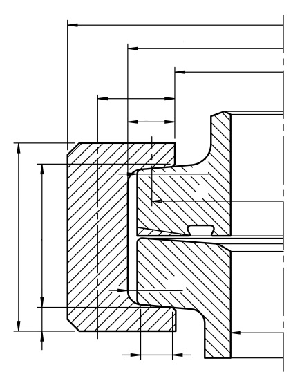
The SPAR module calculates clamping ring connections (clamp closures), in which vessel sections, covers or pipe stubs are joined force-locked via flared ends and a circumferential, split clamping ring. In equipment engineering, such connections frequently replace bolted flanges where quick opening is required – for example on filter housings, sight glasses, manways or in plants with frequent product changes.
The calculation follows the force and stress concept customary for flange connections: from the design pressure, test pressure and design temperature as well as the gasket data – mean gasket diameter, gasket width, gasket factors for the bolt-up and operating conditions, and the safety factor against leakage – the required bolt forces for bolt-up, operation and test are determined. These forces load the clamping ring cross-section via the inclined flanks of the flares; from them, the module calculates bending moments, section moduli and bending, tensile and shear stresses, and reports the equivalent stress with the associated verification condition for each load case.
This makes it possible to calculate and size a clamping ring connection before leak-tightness or load-carrying capacity become a problem in service – including the often overlooked bolt-up condition, in which the full bolt force acts without any relieving internal pressure.
Calculation workflow
- Define the load cases: Design pressure, test pressure and design temperature define the three verification conditions bolt-up, operation and test; the strength values of the clamping ring material are applied as functions of temperature.
- Determine the gasket forces: From the mean gasket diameter, the gasket width and the gasket factors for the bolt-up and operating conditions, the minimum gasket seating stresses are obtained; the safety factor against leakage ensures the required residual gasket stress under operating pressure.
- Calculate the bolt forces of the load cases: For bolt-up, operation and test, the bolt forces are determined from the pressure force on the sealing surface and the required gasket force; the largest value in each case governs the sizing of the closure.
- Determine the internal forces in the clamping ring: The forces introduced via the flare flanks generate bending moments and shear forces in the ring cross-section; with the section modulus of the profile, the bending stress, tensile stress and shear stress are calculated for each load case.
- Perform the equivalent stress verification: From the stress components, the equivalent stress is formed for each load case and compared with the allowable stress; the reported conditions show, for bolt-up, operation and test, whether the clamping ring is adequately sized.
Input quantities
| Quantity | Symbol | Unit |
|---|---|---|
| Design pressure | P | MPa(p) |
| Test pressure | PPr | MPa(p) |
| Design temperature | T | °C |
| Design strength at operating temperature | KT,R | N/mm² |
| Design strength at operating temperature | KT,Fl | N/mm² |
| Design strength at test temperature | KPT,Fl | N/mm² |
| Design strength at test temperature | KPT,R | N/mm² |
| Safety factor at operating conditions | SFB | - |
| Safety factor at test conditions | SFP | - |
| Allowable stress at operating temperature | σzul0,2T,R | N/mm² |
| Allowable stress at test temperature | σzul0,2PT;R | N/mm² |
| Allowable stress at operating temperature | σzul0,2T;Fl | N/mm² |
| Allowable stress at test temperature | σzul0,2PT;Fl | N/mm² |
| Min. allowable stress at operating conditions | Pzul;T | N/mm² |
| Min. allowable stress at test conditions | Pzul;PT | N/mm² |
| Angle of inclination of lug | φ | ° |
| Gap at bolt before tightening | SP | mm |
| Outside diameter of ring | DRa | mm |
| Inside diameter of ring | DRF | mm |
| Onside diameter of lug | DRi | mm |
| Wall thickness of ring | h1 | mm |
| Distance of mean radius of ring to end of lug | l1 | mm |
| Lug length of clamping ring | l2 | mm |
| Chamfer/radius of flange | rR | mm |
Calculated results
| Quantity | Symbol | Unit |
|---|---|---|
| Maximum horizontal clamping force / clamping screw force | FKl,H | N |
| Maximum vertical clamping force | FKl,V | N |
| Bending moment at operating conditions | MSB;AA | N/mm |
| Bending moment at test conditions | MSP;A-A | N/mm |
| Bending moment at installation conditions | MDV;A-A | N/mm |
| Section modulus | WA-A | m³ |
| Bending stress at operating conditions | σbsB,A-A | N/mm² |
| Bending stress at test conditions | σbsP,A-A | N/mm² |
| Bending stress at installation conditions | σbDV,A-A | N/mm² |
| Shear stress at operating conditions | τSB | N/mm² |
| Shear stress at test conditions | τSP | N/mm² |
| Shear stress at installation conditions | τDV | N/mm² |
| Equivalent stress at operating conditions | σVSB,A-A | N/mm² |
| Equivalent stress at test conditions | σVSP,A-A | N/mm² |
| Equivalent stress at installation conditions | σVDV,A-A | N/mm² |
| Condition | B1 | – |
| Condition | B2 | – |
| Condition | B3 | – |
| Bending moment at operating conditions | MSB,B-B | N/mm |
| Bending moment at test conditions | MSP,B-B | N/mm |
| Bending moment at installation conditions | MDV,B-B | N/mm |
| Section modulus | WB-B | m³ |
| Bending stress at operating conditions | σbsB,B-B | N/mm² |
| Bending stress at test conditions | σbsP,B-B | N/mm² |
Frequently asked questions
Why is the bolt-up condition frequently governing for clamping ring connections?
During tightening, the full bolt force acts to seat the gasket, without any internal pressure relieving the connection or the gasket carrying part of the load. With soft gaskets having a high bolt-up gasket factor, the bolt-up bolt force can significantly exceed the operating force – then the bending and equivalent stresses in the bolt-up condition govern the ring sizing, not the operating pressure.
How does the force flow differ from a bolted flange?
In a flange, many bolt forces run parallel to the vessel axis along the bolt circle. In a clamping ring, the axial force and the gasket force are redirected via the inclined flanks of the flares as radial and circumferential loading into the split ring, which is held together by a few clamping bolts. The ring is thus loaded predominantly in bending about its profile axis, and the flank angle determines, via the wedge effect, the ratio of bolt force to generated axial force.
What role do the gasket factors play in the calculation?
The bolt-up factor describes the surface pressure the gasket needs at assembly for initial sealing; the operating factor the residual stress required under internal pressure, multiplied by the safety factor against leakage. Wrong gasket factors, or ones unsuited to the gasket type, lead either to leaking connections or to unnecessarily high bolt forces and thus overstressed rings – the values should be confirmed by the gasket manufacturer for the material and operating temperature.
Are clamp closures suitable for all pressures and nominal sizes?
No. With growing diameter and pressure, the forces to be redirected through the ring increase strongly, so clamping ring connections are economical mainly in the range of small to medium nominal sizes and moderate pressures. Under cyclic loading, gasket creep relaxation and possible spreading of the ring must additionally be considered; for quick-opening closures on pressure vessels, special safety requirements against unintended opening under pressure apply as well.