Engineering task and calculation objective
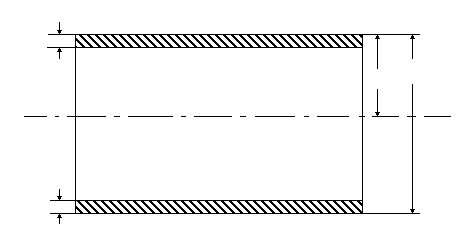
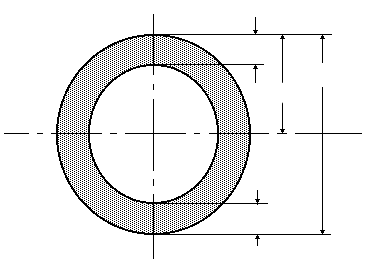
The module calculates the required wall thickness of cylindrical shells under internal pressure according to UG-27 of the ASME Boiler and Pressure Vessel Code, Section VIII Division 1. UG-27 is the fundamental design rule of the American pressure vessel code for cylindrical shells: from the design pressure P, the inside radius R, the allowable stress S of the material at design temperature and the joint efficiency E, the minimum wall thickness is obtained – separately for the circumferential stress (longitudinal seam) and the longitudinal stress (circumferential seam). Conversely, the maximum allowable working pressure (MAWP) can be determined for a given wall thickness.
Anyone who has to calculate a cylindrical shell to ASME needs this verification for every vessel with a U-stamp, and for export projects into markets that require the ASME code – for example North America, the Middle East or large parts of Asia. The allowable stresses S are taken from ASME Section II Part D; the joint efficiency E depends on the extent of non-destructive examination of the seams (fully radiographed E = 1.0, spot examined E = 0.85, not radiographed E = 0.70).
The corrosion allowance and the under-tolerance of the plate or pipe are added to arrive at the final ordered wall thickness. For thick-walled shells and high pressures (t > R/2 or P > 0.385·S·E), UG-27 refers to the equations of Appendix 1-2; this is also the applicability limit of the simple equations.
Calculation workflow
- Define the design data: Design pressure P and design temperature are determined; the inside radius R follows from the vessel diameter, whereby for vessels subject to corrosion the radius enlarged by the corrosion allowance, i.e. in the corroded condition, must be used.
- Determine the material value and the joint efficiency: The allowable stress S is taken from ASME Section II Part D for the selected material at design temperature. The joint efficiency E follows from UW-12 based on the joint type and the extent of examination of the governing seam.
- Calculate the wall thickness for the circumferential stress: With t = P·R/(S·E − 0.6·P), the minimum wall thickness against the circumferential stress (governing for the longitudinal seam) is determined – usually the deciding case, because the circumferential stress is twice as large as the longitudinal stress.
- Check the wall thickness for the longitudinal stress: With t = P·R/(2·S·E + 0.4·P), the verification for the longitudinal stress (circumferential seam) is carried out. It only governs when the circumferential seam has a significantly lower joint efficiency or additional longitudinal forces act.
- Check the applicability limits: The equations apply for t ≤ R/2 and P ≤ 0.385·S·E. If these limits are exceeded, the thick-wall equations of Mandatory Appendix 1-2 must be used.
- Fix the ordered wall thickness: The corrosion allowance and manufacturing or rolling tolerances are added to the calculated minimum wall thickness; the result is then rounded up to an available plate or pipe wall thickness. Optionally, the MAWP is back-calculated for the selected wall thickness.
Input quantities
| Quantity | Symbol | Unit |
|---|---|---|
| Allowable stress | S | – |
| Weld joint efficiency (or Cast Quality Factor) | E | – |
| Calculation pressure | P0 | – |
| Calculation temperature | T0 | – |
| Material | – | – |
| Design wall thickness | te | – |
| Wall thickness allowance | c1 | – |
| Allowance (corrosion) | c2 | – |
| Outside diameter | Do | – |
| Required thickness | t(E=1) | – |
| Design pressure | pD | – |
| Hydrostatic head | Dp | – |
| corroded inside radius | R | – |
| Circumferential weld joint efficiency for Eq. 2 | Ec | – |
Calculated results
| Quantity | Symbol | Unit |
|---|---|---|
| Effective thickness | t0 | – |
| Outside radius | Ro | – |
| Allowable stress | S | – |
| Minimum | t = Max{Min[tR;tR0],tUG-16} t | – |
| thin shell acc. UG-27 | – | – |
| thick shell acc. App.1-2 | – | – |
| Allowable excess pressure | P | – |
| Remark | – | – |
| with allowances | t+c1+c2 | – |
| Allowable excess pressure without hydrostatic head | MAWP | – |
| thin shell acc. UG-27 | – | – |
| thick shell acc. App.1-2 | – | – |
| Calculation as thin shell is applicable | – | – |
| Required wall thickness for circumferential seam | tlong | – |
| Allowable excess pressure for longitudinal stress for Eq. (2) | Plong | – |
| Minimum wall thickness acc. UG-16 | tUG-16 | – |
| Minimum wall thickness without condition acc. UG-16 | tUG-27 | – |
Calculation options
Calculation as thin shell is applicable
No · Yes
Worked example
For a vessel per ASME VIII Div. 1, the minimum wall thickness of the cylindrical shell is to be determined in a worked example. Inside diameter 1,500 mm, design pressure 1.2 MPa (approx. 174 psi), material SA-516 Gr. 70 with an allowable stress S = 138 MPa at design temperature, longitudinal seam fully radiographed (E = 1.0), corrosion allowance 1 mm.
Given values
| Inside diameter Di | 1,500 mm (R = 750 mm) |
| Design pressure P | 1.2 MPa |
| Allowable stress S (SA-516 Gr. 70) | 138 MPa |
| Joint efficiency E | 1.0 (fully radiographed) |
| Corrosion allowance c | 1 mm |
Solution
Check the applicability limits
P = 1.2 MPa ≤ 0.385 · S · E = 0.385 · 138 · 1.0 = 53.1 MPa – the thin-wall equations of UG-27 are applicable.
Wall thickness against circumferential stress (UG-27(c)(1))
t = P · R / (S · E − 0.6 · P) = 1.2 · 750 / (138 · 1.0 − 0.6 · 1.2)
t = 900 / 137.28 ≈ 6.56 mm
Wall thickness against longitudinal stress (UG-27(c)(2))
t = P · R / (2 · S · E + 0.4 · P) = 1.2 · 750 / (2 · 138 + 0.4 · 1.2) = 900 / 276.48 ≈ 3.26 mm
The circumferential stress governs, as expected.
Ordered wall thickness
tmin + c = 6.56 + 1.0 = 7.56 mm → selected: 8 mm plate (plus a check of the rolling tolerance).
Check: t = 8 mm ≤ R/2 = 375 mm – validity limit satisfied.
Result
| Required wall thickness (circumferential stress) | 6.56 mm |
| Required wall thickness (longitudinal stress) | 3.26 mm |
| Selected wall thickness incl. corrosion allowance | 8 mm |
All values are illustrative. The applicable standard and project-specific boundary conditions remain authoritative.
Frequently asked questions
How does UG-27 differ from the European calculation to EN 13445 or AD 2000?
The formula structure is similar, but the safety philosophy differs: ASME Division 1 works with allowable stresses from Section II-D (safety factor 3.5 on the tensile strength), whereas EN 13445 and the German AD 2000 code are primarily based on the yield strength with a factor of 1.5. In addition, UG-27 uses the inside radius R and the term 0.6·P, while the European rules use the diameter and other pressure corrections. The results are therefore not directly interchangeable – the verification must be carried out in whichever code is contractually required.
What does the joint efficiency E mean in concrete terms?
E rates the reliability of the welded seam as a function of joint design and non-destructive examination per UW-12: E = 1.0 for fully radiographed butt welds, E = 0.85 for spot radiography, E = 0.70 without radiography. A low factor directly increases the required wall thickness – forgoing examination is thus paid for in material. For the circumferential stress equation, the longitudinal seam of the shell governs.
Why does the term −0.6·P appear in the denominator of the formula?
It corrects the simple boiler formula for the mean membrane stress to the higher stress at the inner fiber of thin-walled shells. The equation thus remains usefully accurate up to t = R/2 or P = 0.385·S·E. Beyond these limits, the stress distribution across the wall is so non-uniform that the thick-wall equations of Appendix 1-2 must be used.
Is the vessel fully calculated with UG-27?
No. UG-27 delivers only the shell wall thickness against internal pressure. Depending on the vessel, the heads (UG-32), opening reinforcements at nozzles (UG-37), external pressure (UG-28), flanges, support loads and, where applicable, wind and seismic verifications are added. Only the entirety of these verifications yields a code-compliant vessel.