Engineering task and calculation objective
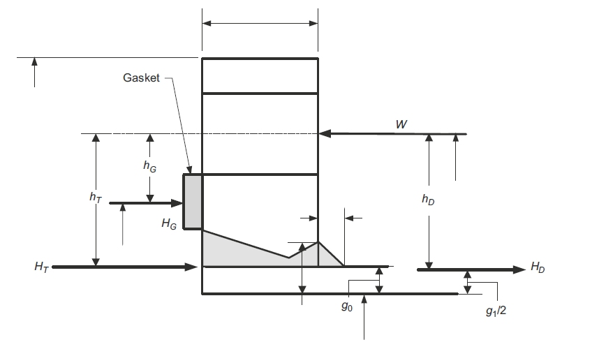
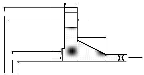
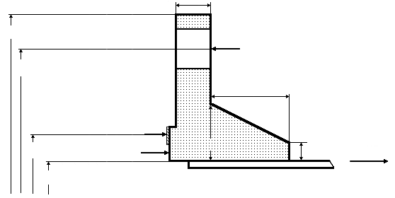
The A416 module performs the flange calculation to ASME BPVC Section VIII, Division 2, paragraph 4.16 (2025 Edition). It covers inserted integral flanges, loose flanges with and without a lapped collar, and designs without a tapered hub — the classic welding-neck, slip-on, and lap-joint configurations of a bolted flange connection with an inside-bolt-circle gasket.
The basis is the Taylor-Forge method in its Division 2 form: from the gasket diameter, gasket width, and effective gasket width per Table 4-16.3, together with the gasket factor m and the gasket seating load y per Table 4-16.1, the bolt forces for the operating and gasket seating conditions are determined. The hoop, radial, and tangential stresses in the flange ring as well as the longitudinal hub stress are then verified against the allowable values of Division 2. For the gasket seating condition, the flange can alternatively be designed for the maximum bolt force — the conservative assumption that assembly exploits the full load capacity of the bolts.
This calculation is needed for every custom flange in pressure vessel design that is not covered by a standardized piping flange (e.g., ASME B16.5) with pressure-temperature ratings: main vessel flanges, tubesheet bolted joints, manway closures. As an additional result the module delivers the maximum allowable working pressure (MAWP) of the joint.
Standard and calculation basis: ASME BPVC VIII-2, A416 2025
Calculation workflow
- Define flange type and geometry: First, the flange type (integral flange, loose flange with/without collar, with/without tapered hub), flange dimensions, bolt circle, and bolt data are defined. The flange type decides whether ring and hub carry the load together (integral) or separately (loose).
- Determine the gasket parameters: From the gasket diameter and gasket width, the effective gasket width b is derived per Table 4-16.3; the gasket factor m and the gasket seating load y come from Table 4-16.1. This yields the load reaction diameter G at which the gasket reaction acts.
- Calculate the bolt forces for both conditions: For the operating condition, the required bolt force is composed of the hydrostatic end force and the residual gasket force (a function of m); for the gasket seating condition, the seating force derived from the seating load y governs. The required bolt cross-sectional area is compared with the actual one; optionally, the seating condition is designed for the maximum bolt force.
- Evaluate moments and lever arms: The component forces (hydrostatic force inside, annular-area force, gasket force) act via their lever arms to the bolt circle and yield the flange moment for the operating and seating conditions — for the loose flange, separately for ring and collar.
- Stress verification and MAWP: From the moments, the longitudinal hub stress and the radial and tangential ring stresses are calculated via the code's shape factors and compared with the allowable stresses of Division 2. In addition, the rigidity criterion (rotation limit) is checked. By inverting the verification, the module determines the maximum allowable working pressure of the joint.
Input quantities
| Quantity | Symbol | Unit |
|---|---|---|
| Calculation temperature | T0 | °C |
| Calculation pressure | P0 | bar |
| Outside diameter Inside diameter | A B | mm |
| Outside diameter Inside diameter | A B | mm |
| Bolt circle diameter Pipe size | C Bn | mm |
| Flange thickness | t | mm |
| Hub length Flange thickness | h t | mm |
| Shell thickness Weld | g1 g0 | mm |
| Shell thickness Weld | g1 g0 | mm |
| Gasket diameter | G | mm |
| Effective gasket width [Table: 4-16.3] | b | mm |
| Gasket factor [Table: 4-16.1] | m | – |
| Gasket seating load [Table: 4-16.1] | y | N/mm² |
| Number | n | – |
| Root diameter | dK | mm |
| Allowable operating stress | Sbo | N/mm² |
| Allowable installation stress | Sbg | N/mm² |
| Required operation bolt load | Wo | N |
| Minimum initial bolt load | Wgs | N |
| Available cross section of bolts | Ab | in² |
| Required cross section | Am1 | in² |
| Required cross section | Am2 | in² |
| Req. bolt load for gasket seating | Wg | lbf |
| Allowable bolt load | Wall | N |
Calculated results
| Quantity | Symbol | Unit |
|---|---|---|
| Cross-sectional area of bolts | – | – |
| Strength condition flange | – | – |
| Flange rigidity | – | – |
| Type | – | – |
Calculation options
Design bolt force
Installation screw force · Maximum permissible screw force · Tightening-controlled screw force
Type
Full flange · Slip-on flange · Loose flange with collar · weld-on flange
Frequently asked questions
How does the flange calculation per VIII-2, 4.16 differ from Appendix 2 of Division 1?
The mechanics are the same Taylor-Forge method, but Division 2 uses its own tables (4-16.1/4-16.3 instead of 2-5.1/2-5.2), higher allowable stresses from the Division 2 safety concept, and a mandatory rigidity criterion against excessive flange rotation. The results are therefore usually leaner, but presuppose the more stringent accompanying requirements of Division 2 (materials, examination, fatigue assessment).
When should the gasket seating condition be designed for the maximum bolt force?
Whenever the assembly preload is not precisely controlled or is deliberately chosen high (e.g., hydraulic tensioning close to the yield strength). Designing for the maximum bolt force ensures that the flange can carry the force that can actually be applied — not only the theoretically required one — without overstressing the ring. It leads to thicker flanges, but prevents ring deformation from over-tightening.
Why can a wider gasket make the joint worse?
With the gasket width, the seating force in the assembly condition rises in proportion to the effective area times the seating load y. A wider gasket means more bolt force, larger moments, and thicker flanges — with no gain in tightness. The code therefore limits the load-bearing width via the effective gasket width b; economically optimal is the narrowest gasket that reliably seals the medium and the load cycles.
Does the calculated MAWP of the flange joint also apply to the vessel?
The maximum allowable working pressure from the module applies only to the flange joint itself. The MAWP of the vessel is the minimum over all components (shells, heads, nozzles, flanges). The flange is frequently the limiting item — particularly at high temperature, when the allowable stresses of the flange and bolt materials drop more steeply than those of the shell.