Engineering task and calculation objective
The FELV module is the general interface between the LV calculation environment and the FEM system COMSOL Multiphysics. It automatically transfers the pressure vessel geometry captured in the analytical modules – shell, dished or flat ends, nozzles, support brackets and other load-bearing attachments – into a parametric finite element model that is then meshed and solved in COMSOL.
In practice, this route is needed whenever rule-based design to AD 2000 (the German pressure vessel code) or EN 13445 reaches its limits: for geometries not covered by the catalogued cases, closely spaced openings, local load introduction through support brackets, or when a stress assessment following the design-by-analysis concept is required. Instead of building the FE model by hand, the user selects the calculation model, head type, nozzle configuration and element size directly in the familiar input mask.
This makes it possible to run a finite element analysis of a pressure vessel without leaving the calculation environment; insulation, the number of bolt holes and the bracket design are taken into account as model parameters.
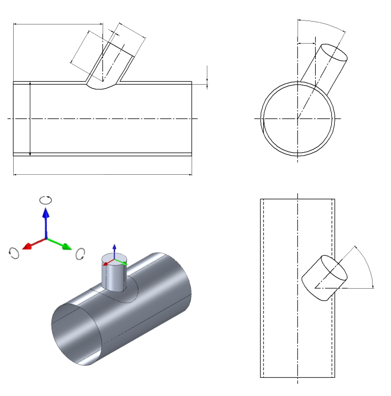
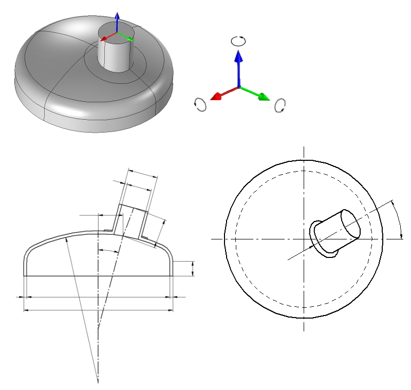
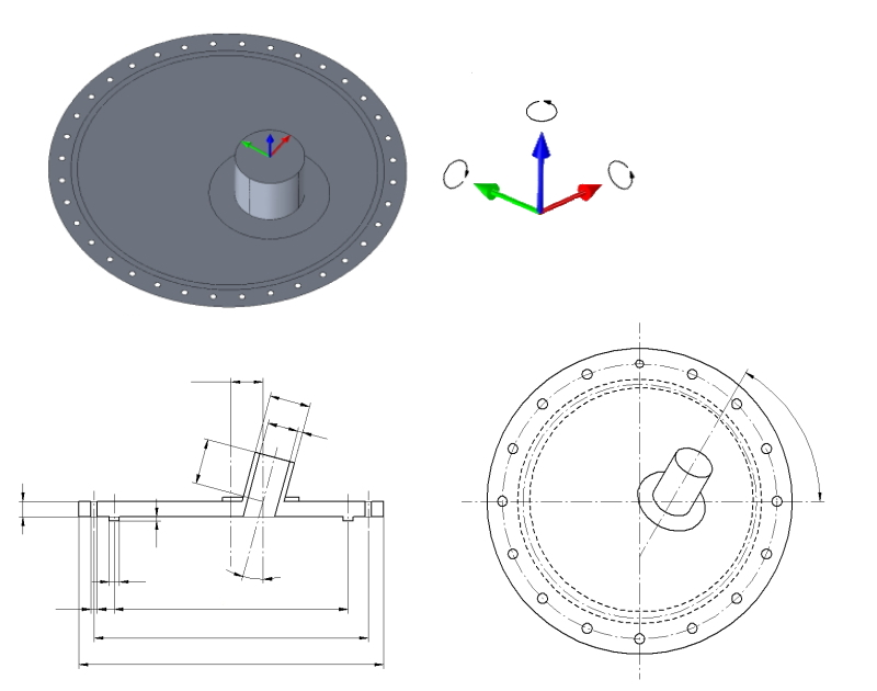
Calculation workflow
- Select the calculation model: The choice of calculation model determines which assembly is to be analyzed – for example a vessel with heads, a flat end with a nozzle, or a bracket-support connection. The selection controls which geometry parameters are subsequently requested.
- Parameterize the geometry: Head type (selectable separately for top and bottom), type of flat end, nominal size, bracket design and the option "nozzle exists" define the model geometry. Additional options such as "with/without insulation" and the number of bolt holes complete the model.
- Define the mesh: The element size sets the mesh refinement. A finer mesh improves accuracy at discontinuities (edges of openings, head-to-shell transitions) but increases computation time.
- Hand over to COMSOL: FELV builds the FE model from the parameters and passes it to COMSOL Multiphysics. There, boundary conditions and loads are applied and the system of equations is solved.
- Return and assess the results: The calculated stresses are returned to the LV environment, where they can be assessed according to the relevant evaluation concepts (e.g. stress categorization per ASME VIII-2 or EN 13445-3 Annex C).
Input quantities
| Quantity | Symbol | Unit |
|---|---|---|
| Select model | Berechnungsmodell | – |
| Outside diameter | Da | mm |
| Length cylindrical shell | L | mm |
| Calculation wall thickness | e | mm |
| Outside diameter nozzle | da | mm |
| Length single nozzle | l | mm |
| Calculation wall thickness | e | mm |
| Welding thickness | a | mm |
| Radial offset | ar | mm |
| Axial displacement | b | mm |
| Inclination single nozzle | θ | ° |
| Rotation nozzle to the axis header | ϕ | ° |
| Diameter reinforcement | da | mm |
| Calculation thickness reinforcement | e | mm |
| Element size | El | mm |
| Modulus of elasticity at 20°C | E20 | N/mm² |
| Modulus of elasticity at 20°C | E20 | N/mm² |
| Calculation temperature | T | °C |
| Calculation pressure | p | MPa(p) |
| Fx | Fx | N |
| Fy | Fy | N |
| Fz | Fz | N |
| Mx | Mx | N·m |
| My | My | N·m |
Calculated results
| Quantity | Symbol | Unit |
|---|---|---|
| Allowable stress | f | N/mm² |
| Allowable stress | f | N/mm² |
| Allowable stress | f | N/mm² |
| Allowable stress | f | N/mm² |
| Allowable stress | f | N/mm² |
| Allowable stress | f | N/mm² |
| lok | lok | N/mm² |
| lok | lok | N/mm² |
| lok | lok | N/mm² |
| lok | lok | N/mm² |
| lok | lok | N/mm² |
| lok | lok | N/mm² |
| Allowable stress | f | N/mm² |
| lok | lok | N/mm² |
| Allowable stress | f | N/mm² |
| Pratze | Pratze | N/mm² |
| Sek | Sek | N/mm² |
| Sek | Sek | N/mm² |
| Sek | Sek | N/mm² |
| Pratze | Pm | N/mm² |
| Pratze | Pb | N/mm² |
| Pratze | Pm+Pb | N/mm² |
| Pratze | Pratze | % |
| Pratze | Pratze | % |
Calculation options
Select model
Spherical dished head with nozzle · Cylindrical shell with single nozzle · Flat head wtih nozzle · Vessel with leg support · Vessel with Saddle Support · Reinforced rectangular vessel · Header with manway · Vessel with bracket support
Select reinforcement
No reinforcement · With reinforcement
Select type of head
Klopper type · Korbbogen type · Hemisphercal end
Select type of flat end
Flanged Flat end · Flat head without additional moment
Leg profile
Round profile · Suqare profile
Execution reinforcement from brim area
From brim rounded reinforcement · From brim rectangular reinforcement
Type base plate
Round base plate · Square base plate
Version
Inserted nozzle · Through nozzle · Attached nozzle
Frequently asked questions
When is an FEM analysis required instead of the design-by-formula approach of AD 2000 or EN 13445?
The design-by-formula rules cover catalogued standard geometries with defined limits of validity. As soon as these limits are exceeded – for example with very large openings, closely spaced nozzles, unsymmetrical load introduction through support brackets, or unusual head shapes – the code itself requires proof by analysis, typically design by analysis to EN 13445-3 Annex B/C or ASME VIII Division 2 Part 5.
Does the user need to know how to operate COMSOL?
No. FELV builds the model parametrically from the mask inputs, starts the calculation and reads the results back. COMSOL works as the solver in the background; however, a COMSOL license or a corresponding calculation service must be available.
How does the chosen element size affect the result?
The element size determines how well stress gradients at notches and discontinuities are resolved. Meshes that are too coarse underestimate local stress peaks; meshes that are too fine yield theoretically unbounded peak values at sharp notches, which can only be assessed meaningfully through stress linearization (membrane/bending stress). A mesh study with at least two refinement levels is good practice.
Are the FEM results automatically checked for admissibility?
The raw FEM results are stress fields, not statements of admissibility. The assessment is carried out via stress categorization (primary membrane, bending and secondary stresses) against the allowable reference values of the selected code. The user remains responsible for the plausibility check of boundary conditions and load assumptions.