Engineering task and calculation objective
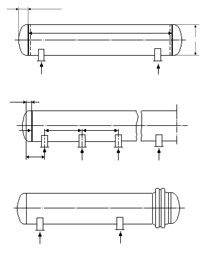
The E168 module verifies horizontal cylindrical vessels on saddle supports to EN 13445-3, Clause 16 (Section 16.8). Statically, a horizontal vessel behaves like a beam on two supports: dead weight and liquid contents produce bending moments and shear forces, which the module evaluates both at mid-span and at the saddle planes. The selected support configuration is taken into account, as are a simultaneously acting external pressure and an additional axial compressive force.
The verification runs on two levels: the strength conditions, in which the longitudinal and shear stresses resulting from the global loads are superimposed on the pressure-induced stresses and checked against the allowable values, and the stability check, which assesses buckling of the shell under axial compression, bending and external pressure. As results, the module reports the utilization of strength and the utilization of stability as well as the evaluated geometrical conditions of applicability of the method.
In practice, this calculation is required for almost every horizontal storage tank, heat exchanger or process vessel – especially under vacuum service or for jacketed vessels, where the combination of saddle loads and external pressure often governs the design long before the pure pressure verification of the shell is exhausted.
Calculation workflow
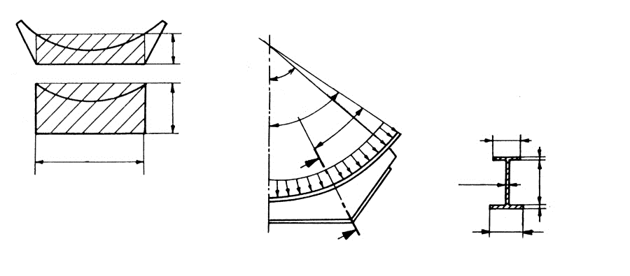
- Define the support configuration and geometry: The saddle support configuration and the geometry of the shell and supports are selected; from these follow the static system quantities for the beam on two supports and the geometrical limits of applicability of the method, which the module also evaluates.
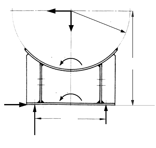
- Determine internal forces: From weight, contents and external loads, the bending moment and shear force are determined or specified at the governing locations – at mid-span and at the saddle planes. In addition, external pressure and axial compressive force are applied as simultaneously acting loads.
- Perform the strength verification: The longitudinal stresses from bending and axial force and the shear stresses from the shear force are superimposed on the pressure stresses and checked against the strength conditions of the standard; the result is reported as the utilization of strength.
- Perform the stability verification: For the compressed regions of the shell, buckling under the combination of axial compression, bending compressive stress and external pressure is verified. The interaction of the load components yields the utilization of stability.
- Assess the results: If both utilizations are below 100 % and the evaluated geometrical conditions are satisfied, the verification is complete. Otherwise, the wall thickness, saddle position, saddle width or reinforcing plates must be adjusted and the calculation repeated.
Input quantities
| Quantity | Symbol | Unit |
|---|---|---|
| Enclosing angle of saddle support plate | δ | ° |
| Enclosing angle of the reinforcement plate | δ2 | ° |
| Wall thickness without allowance | ea = se - c1 - c2 ea | mm |
| Vessel inside diameter | D | mm |
| Reinforcement plate projection | a2 | mm |
| Reinforcement plate thickness | e2 | mm |
| Cylinder length (incl. cylindrical part of head) | L | mm |
| Protruding cantilever length of cylinder | a1 | mm |
| Width of saddle support | b1 | mm |
| Width of reinforcement plate | b2 | mm |
| Nominal wall thickness of vessel | se | mm |
| Weld joint factor | v | - |
| Parameter K11 (acc. section 16.8.4) | K11 | - |
| Density of filling medium | Rf | kg/m³ |
| Calculation pressure | p | bar |
| Calculation temperature | T | °C |
| Material | Behälter | - |
| Material strength | K | N/mm² |
| Safety factor | S | - |
| Manufacturing allowance | c1 | mm |
| Corrosion allowance | c2 | mm |
| Behälter | Nominal design stress f | N/mm² |
| Total weight of vessel (with contents) | W | N |
| Length of head | Hi | mm |
Calculated results
| Quantity | Symbol | Unit |
|---|---|---|
| Enclosing angle of saddle support plate | δ | ° |
| Wall thickness without allowance | ea = se - c1 - c2 ea | mm |
| Reinforcement plate projection | a2 | mm |
| Reinforcement plate thickness | e2 | mm |
| Cylinder length (incl. cylindrical part of head) | L | mm |
| Max. cylinder length (acc. Fig. 16.8-5) | Lmax | mm |
| Protruding cantilever length of cylinder | a1 | mm |
| Width of saddle support | b1 | mm |
| Width of reinforcement plate | b2 | mm |
| Weld joint factor | v | - |
| Parameter K11 (acc. section 16.8.4) | K11 | - |
| Density of filling medium | Rf | kg/m³ |
| Calculation pressure | p | bar |
| Behälter | Nominal design stress f | N/mm² |
| Protruding cantilever length of tank | a1 + 2/3 · Hi a3 | mm |
| Global membrane stress due to bending | Smx | N/mm² |
| (1.25 for operation, 1.05 for testing) | K2 = (16.6-6) | – |
| (16.8-17) | K2 K3 K4 K5 K6 | – |
| (16.8-18) | K2 K3 K4 K5 K6 | – |
| (16.8-19) | K2 K3 K4 K5 K6 | – |
| (16.8-20) | K2 K3 K4 K5 K6 | – |
| (16.8-21) | K7 K8 K9 K10 | – |
| (16.8-22) | K7 K8 K9 K10 | – |
| (16.8-23) | K7 K8 K9 K10 | – |
Calculation options
Type
16.8.4 Conditions for saddles without stress analysis · 16.8.5 Forces and moments at the saddles · 16.8.6 Load limit between the saddles · 16.8.7 Load limit at the saddle without reinforcement plate · 16.8.8 Load limit at the saddle with additional reinforcement plate · 16.6 Line loads due to horizontal forces and moments · AD-S3/2:6 Strength calculation of the saddle
Frequently asked questions
Why are bending moment and shear force evaluated at two locations?
For a beam on two supports, the extreme values occur at different locations: the span moment is maximum at mid-span, while the support moment and the shear force peak above the saddles. Which location governs depends on the saddle spacing – if the saddles move away from the ends, the span moment grows; if they move outward, the support moment and the local stresses at the saddle horn dominate. That is why the standard checks both sections separately.
Why is the load case with external pressure particularly critical?
External pressure produces circumferential compressive stresses and significantly reduces the buckling resistance of the shell. When the bending compressive stresses from the saddle supports are added, two stability-critical loadings are superimposed and must be assessed together in an interaction condition. Vacuum vessels and vessels that steam out during cooldown are therefore often limited by stability rather than by strength.
What can you do if the utilization at the saddle exceeds 100 %?
Proven measures are – in order of effectiveness – moving the saddles closer to the heads (the heads stiffen the shell), adding a wear plate in the saddle region, increasing the saddle contact angle, or increasing the wall thickness. Additional stiffening rings can also be useful under external pressure. A recalculation after every change is essential, since span and support moments change in opposite directions.