Engineering task and calculation objective
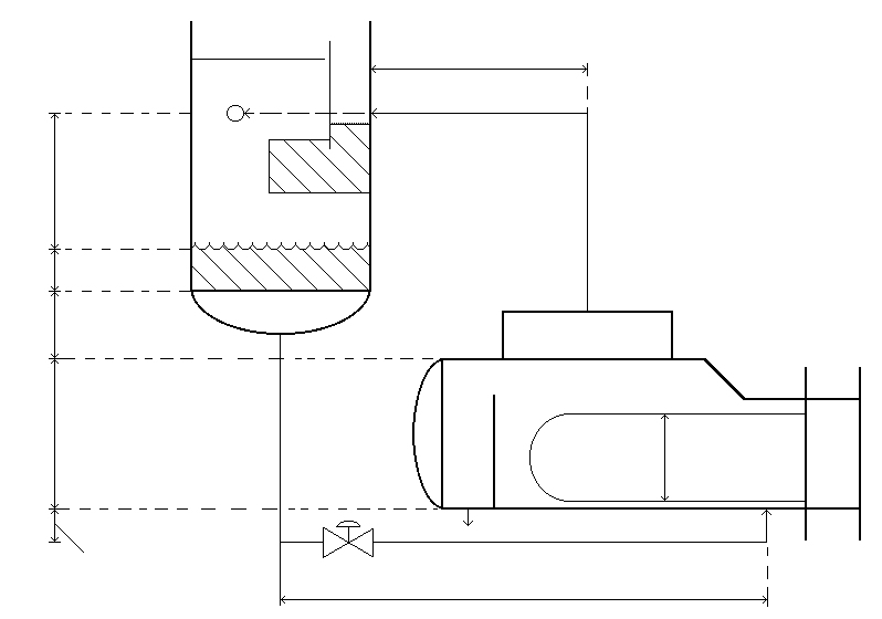
The TSIP module establishes the hydraulic balance for kettle reboilers on distillation columns. A kettle reboiler operates without a pump: the liquid flows from the column sump to the reboiler through the feed line by gravity alone, the generated vapor returns to the column through the vapor line, and an overflow weir in the reboiler keeps the tube bundle covered. For this natural circulation to work, the available static head between column sump and reboiler must exceed the sum of all pressure losses in the liquid and vapor lines – exactly what the hydraulic balance checks.
The module captures both flow paths in detail: for the liquid line, the liquid outlet nozzle of the column, the liquid inlet nozzle of the reboiler, tube bends, tees and valves as resistance coefficients, plus pipe diameter and pipe roughness; for the vapor line, correspondingly the vapor outlet nozzle of the reboiler, the vapor inlet nozzle of the column and the fittings. With the fluid properties (mean density and dynamic viscosity of liquid and vapor) and the mass flows (feed, amount of vapor, outlet at the reboiler end), it calculates velocities, Reynolds numbers, friction factors and the pressure or head losses per meter of line.
The result is the comparison of the head gain (available geodetic height difference) with the sum of all head losses. The balance decides the elevation of the column, the line diameters and, ultimately, whether the reboiler delivers the required amount of vapor without circulation problems.
Calculation workflow
- Record the line routing and resistances: For the liquid line from the column sump to the reboiler and the vapor line back to the column, all individual resistances are compiled: inlet and outlet nozzles, tube bends and tees, and valves; the module forms the sum of the resistance coefficients for each line.
- Define mass flows and fluid properties: The inlet mass flow to the reboiler, the amount of vapor generated and the outlet mass flow at the reboiler end are balanced; the mean density and dynamic viscosity of the liquid and the vapor at the operating point enter as fluid properties.
- Calculate the pressure drop of the liquid line: From pipe diameter, pipe roughness and volume flow follow the flow velocity and Reynolds number; from these, the friction factor, the equivalent resistance coefficient and the pressure drop per meter are determined and converted into meters head of liquid (loss value 1).
- Calculate the pressure drop of the vapor line: Analogously, the velocity, Reynolds number, friction factor and pressure drop per meter are determined for the vapor line and likewise expressed as a head loss in meters head of liquid (loss value 2), so that both lines are comparable in one balance.
- Set up the head balance: The geometric heights – the distance from the lowest point of the piping to the upper edge of the bundle, and the distance from the inlet nozzle of the column to the tangent of the column end – yield the available head gain. This is compared with the friction head losses of both lines and the specified head losses.
- Assess the result: If the head gain exceeds the sum of the losses, the natural circulation works with a margin. Otherwise, larger line diameters, fewer fittings, a higher column elevation or a modified weir in the reboiler are required.
Input quantities
| Quantity | Symbol | Unit |
|---|---|---|
| Distance column center - Inlet nozzle of reboiler | S1 | m |
| Distance vapour inlet nozzle - Liquid surface | S3 | m |
| Head of liquid in column | S4 | m |
| Distance vapour outlet nozzle - vapour inlet nozzle | S7 | m |
| Kettle diameter | DK | m |
| Bundle diameter | DB | m |
| Liquid outlet nozzle of column | WKA | - |
| Liquid inlet nozzle of reboiler | WTE | - |
| Tube bends and tees | WB1 | - |
| Valves | WV1 | - |
| Sum of friction factors | W1 | - |
| Vapour inlet nozzle column | WKE | - |
| Vapour outlet nozzle reboiler | WTA | - |
| Tube bends and tees | WB2 | - |
| Valves | WV2 | - |
| Sum of friction factors | W2 | - |
| Dynamic viscosity of vapour | ηD | kg/(m·s) |
| Dynamic viscosity of liquid | ηF | kg/(m·s) |
| Mean density of vaour | ρD | kg/m³ |
| Mean density of liquid | ρF | kg/m³ |
| Outlet mass flow at reboiler end | mausB | kg/s |
| Amount of vapour | mD | kg/s |
| Inlet mass flow reboiler | mgesT | kg/s |
| Tube diameter | d1 | mm |
Frequently asked questions
How does the kettle reboiler differ hydraulically from a thermosiphon reboiler?
In a kettle reboiler, the liquid evaporates in a large shell space above the bundle; the circulation ratio is uncritical because the overflow weir secures the liquid level and vapor and liquid are separated within the apparatus. The hydraulics reduce to the single-phase feed and vapor lines. In a thermosiphon, by contrast, two-phase flow exists in the riser and the circulation rate establishes itself – the calculation there is considerably more complex and more sensitive.
Why are the pressure losses converted into meters head of liquid?
Because the driving force of the natural circulation is a geodetic height difference, driving head and losses are most easily compared in the same unit: a pressure loss Δp corresponds to a height Δp/(ρ·g) of the sump liquid. The balance "head gain minus sum of head losses" then directly shows the remaining hydraulic margin.
What role does the vapor line play, given how light the vapor is?
A large one: because of the low vapor density, the volume flows are high, and even moderate pressure losses in the vapor line correspond – converted into head of liquid – to considerable head losses. Moreover, a pressure loss in the vapor line raises the pressure and thus the boiling temperature in the reboiler, which reduces the effective temperature difference to the heating medium. Short, generously sized vapor lines without unnecessary fittings are therefore decisive.
What are typical sources of error in the hydraulic balance?
Frequently underestimated are the individual resistances (every bend, every tee, every valve counts), flashing or degassing in the feed line when subcooling is insufficient, and operating cases away from the design point (start-up and shutdown, part load with changed densities). The reference elevations must also be cleanly defined – the lowest point of the piping, the upper edge of the bundle and the nozzle positions must not come from different drawing revisions.