Engineering task and calculation objective
UG-27 is the basic equation of ASME BPVC Section VIII Division 1 for pressure-retaining shells: the paragraph delivers the required wall thickness of cylindrical and spherical shells under internal pressure — and, conversely, the maximum allowable working pressure (MAWP) for an existing wall thickness. This module calculates both directions and adds the alternative formulas of Mandatory Appendix 1, which apply to thick-walled shells beyond the validity limits of UG-27.
For the cylindrical shell, the circumferential (hoop) stress (longitudinal joint) is verified with t = P·R/(S·E − 0.6·P) and the longitudinal stress (circumferential joint) with its own equation; for spherical shells, t = P·R/(2·S·E − 0.2·P) applies. Inputs are the inside radius, the design pressure, the allowable stress S of the material at design temperature and the joint efficiency E from the examination scope per UW-11/UW-12. In addition, the module reports the required wall thickness at 100 % utilization — the reference value tr needed by the opening reinforcement calculation per UG-37.
Calculating the wall thickness of a cylindrical shell to ASME is the starting point of practically every vessel design to VIII-1: from the preliminary sizing at the proposal stage, through the component verification, to the MAWP determination for the nameplate and the test pressure.
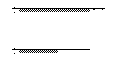
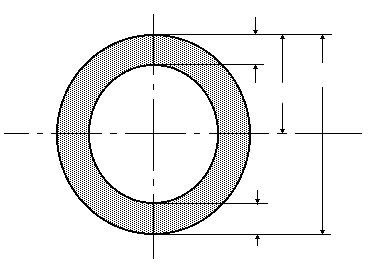
Standard and calculation basis: ASME BPVC VIII-1 UG-27 & Appendix-1: 2025
Calculation scope
- Thickness of cylindrical shells under internal pressure
- Thickness of spherical shells under internal pressure
Calculation workflow
- Define the design data: Inputs are the design pressure, the inside radius (in the corroded condition, i.e. plus corrosion loss), the material with its allowable stress S at design temperature and the joint efficiency E, which follows from the joint type and the radiographic examination scope per UW-11/UW-12.
- Calculate the required wall thickness: For the cylindrical shell, the wall thickness is determined from the circumferential stress equation t = P·R/(S·E − 0.6·P); in addition, the longitudinal stress equation is checked, which becomes governing only with additional axial loads or a small circumferential joint efficiency. For spherical shells, t = P·R/(2·S·E − 0.2·P) applies.
- Check the validity limits: The UG-27 formulas apply for t ≤ 0.5·R and P ≤ 0.385·S·E (cylinder). For thick-walled shells or higher pressures, the module switches to the equations of Mandatory Appendix 1, which are based on the thick-wall solution.
- Allowances and as-built thickness: The corrosion allowance and, where applicable, the undertolerance of plate or pipe are added to the calculated thickness; this yields the ordering or as-built thickness. The minimum thickness per UG-16 (1.6 mm) must be observed.
- Report the allowable pressure and tr: Conversely, the module calculates the MAWP of the shell from the existing wall thickness (minus allowances). Additionally, the required wall thickness at 100 % utilization (E = 1.0) is output — the value tr that the opening reinforcement per UG-37 uses as its reference.
Input quantities
| Quantity | Symbol | Unit |
|---|---|---|
| Allowable stress | S | MPa |
| Weld joint efficiency (or Cast Quality Factor) | E | – |
| Calculation pressure | P0 | MPa(p) |
| Calculation temperature | T0 | °C |
| Material | Werkstoff | – |
| Design wall thickness | te | mm |
| Wall thickness allowance | c1 | mm |
| Allowance (corrosion) | c2 | mm |
| Outside diameter | Do | mm |
| Required thickness | t(E=1) | mm |
| Design pressure | pD | MPa |
| Hydrostatic head | Dp | MPa |
| corroded inside radius | R | mm |
| Circumferential weld joint efficiency for Eq. 2 | Ec | – |
Calculated results
| Quantity | Symbol | Unit |
|---|---|---|
| Effective thickness | t0 | mm |
| Outside radius | Ro | mm |
| Allowable stress | S | MPa |
| Minimum | t = Max{Min[tR;tR0],tUG-16} t | mm |
| thin shell acc. UG-27 | t(1) | mm |
| thick shell acc. App.1-2 | t(2) | mm |
| Allowable excess pressure | P | MPa(p) |
| Remark | 1 | – |
| with allowances | t+c1+c2 | mm |
| Allowable excess pressure without hydrostatic head | MAWP | MPa |
| thin shell acc. UG-27 | UG-27 | mm |
| thick shell acc. App.1-2 | App.1-2 | mm |
| Calculation as thin shell is applicable | (Y/N) | – |
| Required wall thickness for circumferential seam | tlong | mm |
| Allowable excess pressure for longitudinal stress for Eq. (2) | Plong | MPa(p) |
| Minimum wall thickness acc. UG-16 | tUG-16 | mm |
| Minimum wall thickness without condition acc. UG-16 | tUG-27 | mm |
Calculation options
Calculation as thin shell is applicable
No · Yes
Worked example
For a cylindrical shell per ASME VIII-1 UG-27, the required wall thickness and the MAWP of the selected design are to be determined.
Given values
| Design pressure P | 1.6 MPa (16 bar) |
| Inside radius R (corroded) | 500 mm |
| Material SA-516 Gr. 70, allowable stress S | 138 MPa |
| Joint efficiency E (full radiography) | 1.0 |
| Corrosion allowance c | 1.0 mm |
Solution
Applicability of the UG-27 equation
P = 1.6 MPa ≤ 0.385·S·E = 0.385 · 138 · 1.0 = 53.1 MPa — thin-wall equation permissible.
Required wall thickness (circumferential stress)
t = P·R / (S·E − 0.6·P) = 1.6 · 500 / (138 · 1.0 − 0.6 · 1.6)
t = 800 / 137.04 = 5.84 mm
With corrosion allowance: t + c = 5.84 + 1.0 = 6.84 mm → selected 8.0 mm plate.
MAWP of the selected design
Load-bearing wall thickness: teff = 8.0 − 1.0 = 7.0 mm
MAWP = S·E·teff / (R + 0.6·teff) = 138 · 1.0 · 7.0 / (500 + 0.6 · 7.0)
MAWP = 966 / 504.2 = 1.92 MPa (19.2 bar)
Result
| Required wall thickness (without allowance) | 5.84 mm |
| Selected plate thickness | 8.0 mm |
| MAWP (corroded) | 1.92 MPa ≈ 19.2 bar |
All values are illustrative. The applicable standard and project-specific boundary conditions remain authoritative.
Frequently asked questions
Why does the term 0.6·P appear in the denominator of the cylinder formula?
The boiler formula t = P·R/(S·E) strictly applies only to the membrane surface of thin-walled shells. The term −0.6·P corrects the equation so that it approximately captures the higher stress at the inner fiber of thicker walls — it thereby remains usable up to t = 0.5·R and P = 0.385·S·E. For the sphere, the correction term is −0.2·P, since the sphere carries only half the hoop stress.
Which radius is used in the calculation — new or corroded?
Always the corroded condition: the inside radius grows by the corrosion allowance, and the load-bearing wall thickness is the as-built thickness minus the allowance. Calculating with as-new dimensions overestimates the MAWP over the service life. Also when re-rating existing vessels, the measured actual condition (remaining wall thickness, expanded radius) must be used.
What does the joint efficiency E mean and what does it depend on?
E rates the longitudinal joint of the shell according to the non-destructive examination scope per UW-11/UW-12: E = 1.0 for full radiography, 0.85 for spot radiography (spot RT), 0.70 without radiography. For the circumferential stress equation the longitudinal joint counts; for the longitudinal stress equation the circumferential joint. A lower examination scope is thus directly paid for with more wall thickness — an economic trade-off between examination cost and material use.
Why does UG-37 need the wall thickness at 100 % utilization?
The opening reinforcement per UG-37 compares available excess thicknesses with the required thickness tr, which by definition is calculated with E = 1.0 — the weld quality is captured there by its own rules. That is why the module outputs, alongside the actual required thickness, also tr at full utilization; confusing the two values is a typical error source in nozzle verifications.