Engineering task and calculation objective
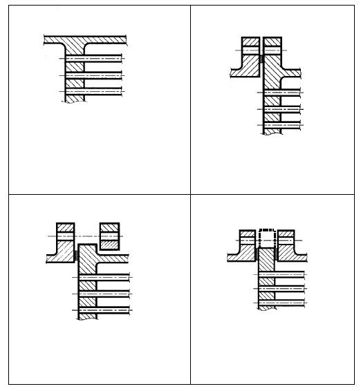
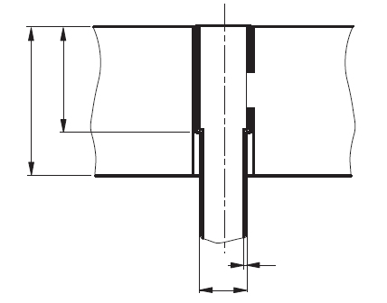
The E13B module belongs to the tubesheet calculation for shell-and-tube heat exchangers to EN 13445-3, Clause 13, and deals with the connection and gasket geometry of the tubesheet. It records the tube layout (tube hole pitch, largest center-to-center distance between adjacent tube rows per Fig. 13.7.3-1, depth of the pass partition groove per Fig. 13.7.3-2, untubed areas per Fig. 13.7.3-5), the gasket data for both sides (contact face diameters, basic gasket seating width, diameter of the gasket load, gasket factor) as well as the flange connection with bolt circle, number of bolts, bolt hole diameter and assembly bolt force.
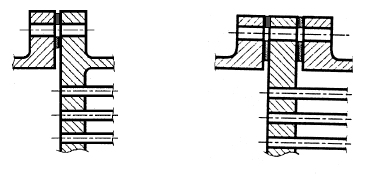
For fixed tubesheet heat exchangers with an expansion bellows, the axial rigidity of the bellows and its inside diameter are entered in addition – they decide how strongly differential thermal expansion between the tube bundle and the shell loads the tubesheet. From the tube layout geometry the module derives the effective characteristic values per Clause 13.7 (effective tube pitch, effective tube hole diameter, ligament efficiencies, effective modulus of elasticity, effective Poisson's ratio, effective bending stiffness and effective tubesheet radius) and, for perforated tubesheets with a flange extension per Clauses 13.10 or 13.11, determines the governing moment and the required flange thickness.
This calculation is standard practice when designing shell-and-tube heat exchangers under the Pressure Equipment Directive: it combines the tightness and bolt verification of the flange connection with the strength verification of the perforated tubesheet.
Calculation workflow
- Describe the tube layout and untubed zones: Tube hole pitch, largest tube row spacing, depth of the pass partition groove and the untubed areas per Fig. 13.7.3-5 define the perforated region. The diameter of the perforated area is checked against the condition ≥ 0.85 · De.
- Define the gaskets on both sides: For the shell side and the channel side, the outside and inside diameters of the contact face are entered; from these follow the basic gasket seating width, the effective gasket width and the diameter of the gasket load. The gasket factor determines the required seating pressures.
- Verify the bolted connection and the assembly condition: From the bolt circle diameter, the number of bolts and the bolt hole diameter, together with the allowable assembly stress of the flange, the assembly bolt force is determined, which acts as an edge load on the tubesheet.
- Account for the bellows rigidity: For fixed tubesheet designs with an expansion bellows, the axial rigidity of the bellows is entered; without a bellows, a very high rigidity is assumed in the calculation. The bellows decouples the thermal expansion of bundle and shell and thus reduces the restraint forces acting on the tubesheet.
- Calculate effective characteristics and required thickness: In accordance with Clause 13.7, the effective tube pitch, effective tube hole diameter, ligament efficiencies, effective modulus of elasticity, Poisson's ratio and bending stiffness of the tubesheet are determined. With the moment per equation (13.11.5-2) or (13.10.5-4), the required flange thickness of the tubesheet with flange extension follows.
Input quantities
| Quantity | Symbol | Unit |
|---|---|---|
| Tubesheet material | Boden | – |
| Thickness | Bodendicke | mm |
| Outside diameter | Boden | mm |
| Strength (Testing) | Prüfung | MPa |
| Strength (Operation) | Betrieb | MPa |
| Safety factor (Testing) | Prüfung | – |
| Safety factor (Operation) | Betrieb | – |
| Modulus of elasticity | **) | MPa |
| Allowance c1 | Boden | mm |
| Corrosion allow. c2 | Boden | mm |
| Therm. exp. | Boden | 1E-6/°C |
| Load case (1=operation, 2=test at 20°C, 3=other) | 2=Prüfung) | – |
| Lastfallbezeichnung | *) | – |
| Yield point | Boden | MPa |
| Allowable stress | *) | MPa |
| for calculation case | σs,eq = < fs = 1-3 | MPa |
| Yield strength of shell at | Ts = Sy1s | °C |
| Shell material (Type abc) | Mantel | – |
| Internal calculation pressure shell side | Ps | MPa |
| Thickness | Manteldicke | mm |
| Outside diameter | Mantel | mm |
| Strength (Testing) | Prüfung | MPa |
| Strength (Operation) | Betrieb | MPa |
| Safety factor (Testing) | Prüfung | – |
Calculated results
| Quantity | Symbol | Unit |
|---|---|---|
| Effective tubesheet diameter | De | mm |
| Channel inside diameter corroded (type a) | Dc | mm |
| Channel shell thickness without allowances | tc | mm |
| Shell thickness without allowances | ts | mm |
| Stiffness ratio Kj/(Ks+Kj) (=1 without bellows) | J | – |
| Shell inside diameter corroded (type abc) | Ds | mm |
| Effective tubesheet radius | (13.5.4-1) De/2 | mm |
| Stiffness tube-bundle/tubesheet | (13.5.4-12) X | – |
| Type abc: Coefficient for shell pressure | (13.5.4-13) ks | N |
| Type a: Coefficient for channel press. | (13.5.4-15) kc | N |
| Min. shell length of constant thickness | (13.5.2-8) lsm | mm |
| Min. channel length of constant thickness | (13.5.2-12) lcm | mm |
| Parameter = 1-Nt · (0.5 · daTUBE/a0)2 | (13.5.4-5) xs | – |
| Parameter = 1-Nt · (0.5·diTUBE/a0)2 | (13.5.4-6) xt | – |
| Shell axial rigidity Ks (Ks*) | (13.5.4-8) Ks | N/mm |
| Tube axial rigidity | (13.5.4-7) Kt | N/mm |
| Stiffness ratio Ks / (Nt· Kt) | (13.5.4-9) Kst | – |
| Tube bundle elastic foundation factor | (13.5.4-10) Kw | N/mm^3 |
Frequently asked questions
When do you calculate to Clause 13.10 and when to Clause 13.11 of EN 13445-3?
Both clauses deal with tubesheets with a flanged connection: Clause 13.11 applies to tubesheets with a machined flange extension (hub thickness g1 > 0), Clause 13.10 to the simplified configuration without a load-bearing extension (g1 = 0). The module distinguishes the cases via the entered hub thickness and uses the corresponding moment equation, (13.11.5-2) or (13.10.5-4), for the required flange thickness.
What role does the axial rigidity of the bellows play?
In fixed tubesheet heat exchangers, both tubesheets are rigidly connected to shell and bundle; differential thermal expansion then produces high axial forces in the tubes and the shell and corresponding loads on the tubesheet. An expansion bellows in the shell acts as a soft spring in series: the lower its axial rigidity, the smaller the restraint forces. If no bellows is installed, a practically infinite rigidity (e.g. 1E+38) must be entered so that the shell carries the full load in the calculation.
Why are untubed areas and pass partition grooves recorded separately?
Untubed zones – for example under baffle segments or along pass partitions – locally stiffen the plate, while the pass partition groove on the channel side reduces the load-bearing thickness. The standard therefore corrects the ligament efficiency using the untubed area (Fig. 13.7.3-5) and subtracts the effective groove depth from the plate thickness. Omitting these inputs makes the tubesheet calculation either unconservative or unnecessarily conservative, depending on the case.