Engineering task and calculation objective
The E13A module is part of the tubesheet calculation for shell-and-tube heat exchangers to EN 13445-3, Clause 13. This input form collects the material- and cross-section-related fundamentals of the verification: design strength values, safety factors, moduli of elasticity, yield strengths and tensile strengths of the components involved (tubesheet, tubes, shell and channel) as well as the bolt forces in the assembly condition for the channel flange and the shell flange.
Building on this, the characteristic values of the perforated tubesheet are determined in accordance with Clause 13.7 of the standard: the effective tube pitch, the effective tube hole diameter, the basic ligament efficiency of the tube pattern together with the effective ligament efficiency, plus the effective modulus of elasticity and effective Poisson's ratio of the perforated plate from the curves in Fig. 13.7.8-1 and -2. The diameter ratio and the coefficients derived from it finally lead to the governing bending moments – the maximum moment at the plate periphery and the moment at the tubesheet center.
Anyone who needs to calculate a tubesheet to EN 13445, for example for a heat exchanger under the Pressure Equipment Directive, cannot avoid this equivalent-plate methodology: the multiply drilled tubesheet is treated as a homogeneous plate with reduced elastic constants, and all subsequent stress verifications rely on the effective values determined here.
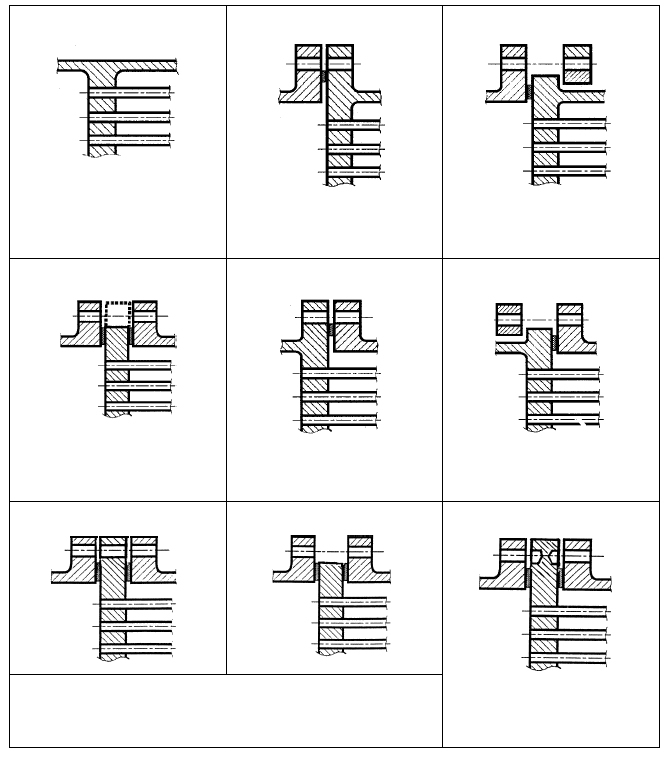
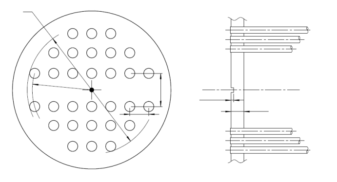
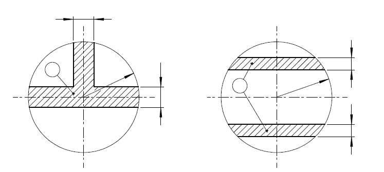
Calculation workflow
- Record material data for the component groups: For the tubesheet, tubes, shell and channel, the design strength, safety factor, modulus of elasticity, yield strength and tensile strength at design temperature are entered. They determine the allowable stresses of the individual heat exchanger components.
- Take over flange and bolt data: The bolt circle diameter and the bolt forces in the assembly condition for the channel flange and the shell flange enter the tubesheet calculation as edge loads, since in bolted designs the tubesheet must also carry the flange moments.
- Describe the tube layout geometry: The geometry of the perforated region is fully defined by the equivalent diameter of the outer tube limit circle, the effective tube pitch, the effective tube hole diameter and the effective depth of the pass partition groove.
- Determine effective elastic constants: In accordance with Clause 13.7 of EN 13445-3, the basic ligament efficiency of the tube pattern, the effective ligament efficiency, and the effective modulus of elasticity and effective Poisson's ratio of the tubesheet are determined from the curves in Fig. 13.7.8-1 and -2. The perforated plate is thereby replaced, for calculation purposes, by a homogeneous equivalent plate.
- Calculate the governing moments: Using the diameter ratio A/D0 and the associated coefficients, the maximum bending moment at the plate periphery and the moment at the tubesheet center are determined – the basis for the stress and thickness verification of the tubesheet.
Input quantities
| Quantity | Symbol | Unit |
|---|---|---|
| Material tubesheet | Boden | – |
| Thickness | e = = tvB - c1B - c2B = - - | mm |
| Outside diameter | A5 | mm |
| Strength | KBp6 | N/mm² |
| Strength | KB7 | N/mm² |
| Safety factor | SBp8 | – |
| Safety factor | SB9 | – |
| Modulus of elasticity **) | EBp10 | N/mm² |
| Modulus of elasticity **) | EB11 | N/mm² |
| Allowance c1 | e = = tvB - c1B - c2B = - - | mm |
| Corros. allow. c2 | e = = tvB - c1B - c2B = - - | mm |
| Thermal expansion | alf15 | 1E-6/°C |
| Load case | lc16 | – |
| Yield strength | SgB19 | N/mm² |
| Tensile strength | SzB20 | N/mm² |
| All. Stress *) | SigB21 | N/mm² |
| Material shell | WM24 | – |
| Internal calculation pressure shell side | Ps | MPa |
| Thickness | tvM26 | mm |
| Outside diameter | daM27 | mm |
| Strength | KMp28 | N/mm² |
| Strength | KM29 | N/mm² |
| Safety fac. | SMp30 | – |
| Safety fac. | SM31 | – |
Calculated results
| Quantity | Symbol | Unit |
|---|---|---|
| Thickness | e = = tvB - c1B - c2B = - - | mm |
| Allowance c1 | e = = tvB - c1B - c2B = - - | mm |
| Corros. allow. c2 | e = = tvB - c1B - c2B = - - | mm |
| Thickness | tT = = tvT - c1T - c2T = - - | mm |
| Allowance c1 | tT = = tvT - c1T - c2T = - - | mm |
| Corros. allow. c2 | tT = = tvT - c1T - c2T = - - | mm |
| Tubesheet thickness without allowances > hin | e | mm |
| Rohrdicke | tT = = tvT - c1T - c2T = - - | mm |
| Inside diameter of channel, corroded | Dc | mm |
| Channel thickness without allowances | tc | mm |
| Shell thickness without allowances | ts | mm |
| Maximum bolt force | Wmax | N |
| GS/D0 | Ds/D0 (Typ a,b,b',c), Gs/D0 (Typ d,d',e,e',f) ρs | – |
| GC/D0 | Dc/D0 (Typ a,e,e',f), Gc/D0 (Typ b,b',c,d,d') ρc | – |
| Inside diameter of shell, corroded | Ds | mm |
| Recommended initial tubesheet thickness 13.4.4.2 | ein | mm |
| Tubesheet rim moment due to Ps and Pt | = + - + | N |
| betaS | βs ks λs | 1/mm |
| kS | βs ks λs | N |
| lambdaS | βs ks λs | N/mm² |
| Coefficient for shell pressure | Ps' | mm |
| Boundary moment due to shell pressure | = + - + | N |
| betaC | βc kc λc | 1/mm |
| kC | βc kc λc | N |
Frequently asked questions
Why does EN 13445 use an effective modulus of elasticity for the tubesheet?
Because of its many tube holes, a tubesheet is considerably more flexible and weaker than a solid plate. Instead of modeling every hole individually, the standard replaces the perforated plate with a homogeneous equivalent plate with a reduced modulus of elasticity and an adjusted Poisson's ratio, read from the curves in Fig. 13.7.8-1 and -2 as a function of the effective ligament efficiency and the thickness-to-pitch ratio. The equivalent plate yields the same global deflections and internal forces as the real, perforated tubesheet.
What is the difference between the basic and the effective ligament efficiency?
The basic ligament efficiency describes the ratio of the load-bearing ligament cross-section to the unweakened pitch, based solely on the tube hole diameter and pitch. The effective ligament efficiency additionally accounts for the fact that expanded or welded tube ends carry load (effective tube hole diameter) and that pass partition grooves and untubed zones locally weaken or stiffen the plate. For the bending verification, the effective value always governs.
Why do the flange bolt forces enter the tubesheet calculation?
For tubesheets bolted between flanges or with a bolted-on channel, the bolt forces at the bolt circle create an edge moment on the plate. This assembly moment is superimposed on the pressure-induced moments and can be the governing load case, particularly in the assembly condition without internal pressure. The standard therefore requires verification of both the assembly and the operating conditions.