Engineering task and calculation objective
The E13C module covers the bundle part of the tubesheet calculation for fixed tubesheet heat exchangers to EN 13445-3, Clause 13. In addition to the tube layout geometry (tube hole pitch, tube row spacings per Fig. 13.7.3-1, pass partition groove, untubed areas), the bundle data are entered here: number of tubes, number and spacing of the baffles, distance from the tubesheet to the first baffle, the tube length between the tubesheets and the unsupported tube span for the buckling check of the tubes.
The core of the calculation model: for the tubesheet, the tube bundle acts as an elastic foundation. From the axial stiffness of a single tube and the number of tubes, the elastic foundation factor of the bundle is obtained, and from the ratio of the bundle and tubesheet stiffnesses the dimensionless parameter X. Together with the edge restraint factor Z – from simply supported (Z = 0) to fully clamped (Z > 5) – and the configuration-dependent coefficients for shell-side and channel-side pressure, this yields the effective pressure with which the tubesheet, the tubes and the joints are verified.
This calculation is required for every fixed tubesheet heat exchanger to EN 13445, because there the shell, the tubes and both tubesheets form a statically indeterminate system: pressure differences and thermal expansions are distributed between tubesheet and bundle according to their stiffnesses – analyzing the components separately would be unsafe.
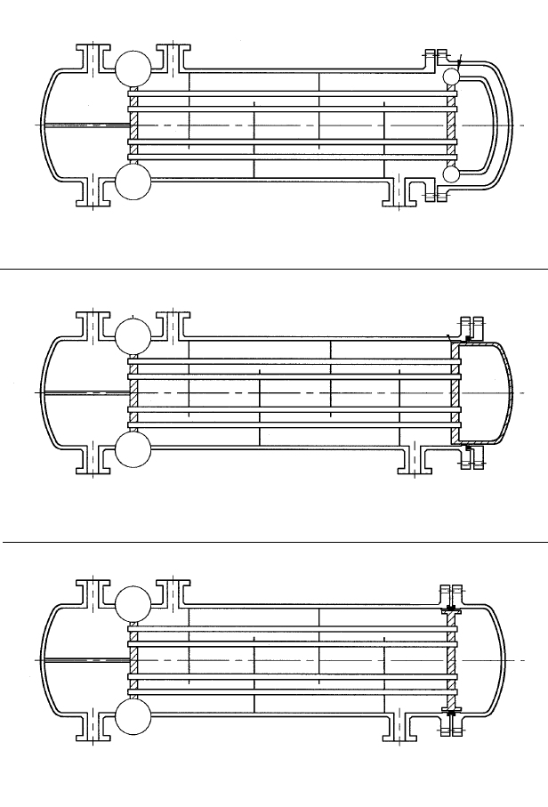
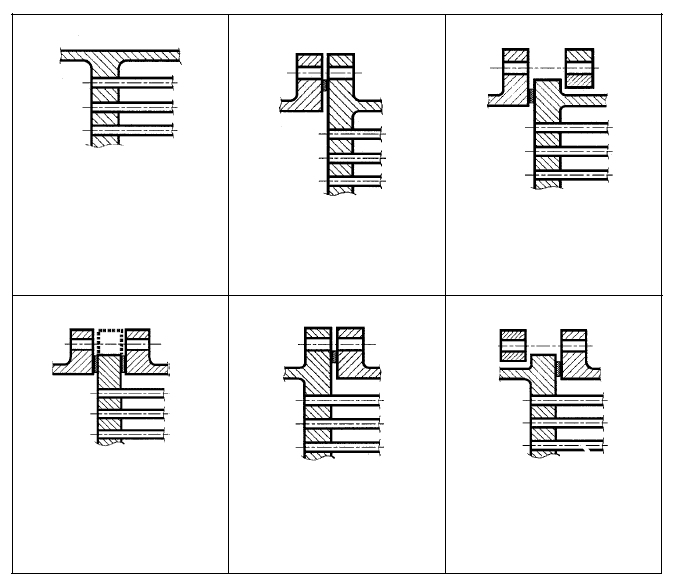
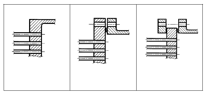
Calculation workflow
- Record tube layout and bundle geometry: Tube hole pitch, number of tubes, untubed areas and pass partition groove describe the perforated tubesheet; the tube length between the tubesheets, the number and spacing of the baffles and the unsupported span define the bundle for the buckling check of the tubes.
- Assign flange and gasket data: Bolt circle diameter, number of bolts, bolt hole diameter, gasket factor, gasket contact width and assembly bolt force provide the edge loads of the tubesheet at the bolted connection per Clauses 13.10 or 13.11.
- Determine effective plate characteristics: In accordance with Clause 13.7, the effective tube pitch, effective tube hole diameter, ligament efficiencies, effective modulus of elasticity, effective Poisson's ratio as well as the effective bending stiffness and the effective radius of the equivalent plate are calculated.
- Calculate the elastic foundation provided by the tube bundle: From the axial stiffness of one tube and the number of tubes, the elastic foundation factor of the bundle follows; the stiffness ratio bundle/tubesheet gives the parameter X, which governs the load-bearing behavior of the plate on an elastic foundation.
- Determine the effective pressure and run the verifications: With the configuration-dependent coefficients for shell-side and channel-side pressure (configuration types a, b, c) and the edge restraint factor Z, the effective pressure is calculated. It is then used to verify the bending stress of the tubesheet, the axial stresses of the tubes including buckling safety over the unsupported span, and the tube-to-tubesheet joint.
Input quantities
| Quantity | Symbol | Unit |
|---|---|---|
| Tubesheet material | Boden | – |
| Thickness | Bodendicke | mm |
| Outside diameter | Boden | mm |
| Strength test | Prüfung | MPa |
| Strength operat. | Betrieb | MPa |
| Safety test | Prüfung | – |
| Safety operation | Betrieb | – |
| Modulus of elasticity | **) | MPa |
| Allowance c1 | Boden | mm |
| Corros.allow. c2 | Boden | mm |
| Thermal expans. | Boden | 1E-6/°C |
| Load case (1=operation, 2=test at 20°C, 3=other) | 2=Prüfung) | – |
| Lastfallbezeichnung | Lastfallbezeichnung | – |
| Yield strength | Boden | MPa |
| Allow. stress | *) | MPa |
| Shell material (Type abcd'e') | Mantel | – |
| Internal calculation pressure shell side | Ps | MPa |
| Thickness | Manteldicke | mm |
| Outside diameter | Mantel | mm |
| Test stren. | Prüfung | MPa |
| Op.strength | Betrieb | MPa |
| Test safety | Prüfung | – |
| Oper.safety | Betrieb | – |
| Modulus of elasticity | **) | MPa |
Calculated results
| Quantity | Symbol | Unit |
|---|---|---|
| Effective tubesheet diameter | De | mm |
| Channel inside diameter corroded (type ab'd'ef) | Dc | mm |
| Channel shell thickness without allowances | tc | mm |
| Shell thickness without allowances | ts | mm |
| Shell inside diameter corroded (type abcd'e') | Ds | mm |
| Effective tubesheet radius | (13.6.4-1) De/2 | mm |
| Stiffness bundle/tubesheet | (13.6.4-9) X | – |
| Type abc: Coefficient for Shell press. | (13.6.4-10) ks | N |
| Type a: Coefficient for Channel press. | (13.6.4-11) kc | N |
| Min. shell length of constant thickness | (13.6.2-8) ls,m | mm |
| Min. channel length of constant thickness | (13.6.2-13) lc,m | mm |
| Type of tube support (0.6=tubesheet-tubesheet, 0.8=tubesheet - support plate, 1=plate-plate ) | k | – |
| Parameter | 1-Nt · (0.5 · daTUBE/a0)2 (13.6.4-5) xs | – |
| Parameter | 1-Nt · (0.5 · diTUBE/a0)2 (13.6.4-6) xt | – |
| Axial stiffness of one tube | (13.6.4-7) Kt | N/mm |
| Required flange thickness for type b, b' | efl | mm |
| Required flange thickness for type e, e' | efs | mm |
| Moment acc. (13.11.5-2) or (13.10.5-4) type b,b' | Mr,c | Nm |
| Moment acc. (13.11.5-2) or (13.10.5-4) type e,e' | Mr,s | Nm |
| Equivalent free buckling length | k*l (13.9.3-2) lt | mm |
| Elastic foundation factor tube bundle | (13.6.4-8) Kw | N/mm^3 |
| Tube edge restraint factor (Z=0: simply supported, Z>5: clamped ) | (13.6.4-12) Z | – |
| Effective pressure | *) (13.6.4-13/14) Pe | MPa |
Frequently asked questions
What does the elastic foundation of the tubesheet by the tube bundle mean?
In fixed tubesheet heat exchangers, the welded or expanded tubes support the tubesheet like a field of springs: every deflection of the tubesheet stretches or compresses the tubes axially, which then generate restoring forces. EN 13445-3 models this as a plate on an elastic foundation; the foundation factor is the axial stiffness of one tube times the number of tubes, referred to the tubesheet area. The stiffer the bundle relative to the tubesheet (large parameter X), the more load the tubes carry and the thinner the tubesheet can be – at the price of higher axial loading of the tubes.
What is the edge restraint factor Z for?
Z describes how strongly the shell and the channel restrain the rotation of the tubesheet edge: Z = 0 corresponds to a simply supported edge, Z > 5 to a practically clamped one. The restraint shifts the governing bending moment from the center of the tubesheet to the edge and thus influences both the required tubesheet thickness and the loading of the tubes near the edge. Z follows from the stiffnesses of the connected shells relative to the bending stiffness of the tubesheet.
Why is an unsupported span needed for the buckling check of the tubes?
On the higher-pressure side, the tubes can be loaded axially in compression. What governs the buckling safety is the largest unsupported length between the tubesheet and the first baffle, or between two baffles – with staggered, slotted baffles possibly spanning two bays. The baffles act as lateral support points; their number and spacing therefore determine not only the flow pattern but also the allowable compressive force of the tubes.
What distinguishes the configuration types a, b and c?
For fixed tubesheet heat exchangers, EN 13445-3 distinguishes how the tubesheet is connected to the shell and the channel – integrally welded or connected via gasket and bolts. Separate coefficients apply for each configuration when converting shell-side and channel-side pressure into the effective pressure, because the pressurized areas and the edge moments differ. The module reports the coefficients for shell-side pressure (types a, b, c) and channel-side pressure (type a) separately.