Engineering task and calculation objective
The UG34 module calculates unstayed flat heads, covers and plates to ASME BPVC Section VIII Division 1, paragraph UG-34, supplemented by the opening rules of UG-39. Flat heads are used in equipment fabrication wherever formed heads would be too elaborate: as forged or welded-in closure plates, as blind covers, and as bolted plates on handholes and heat exchanger channels.
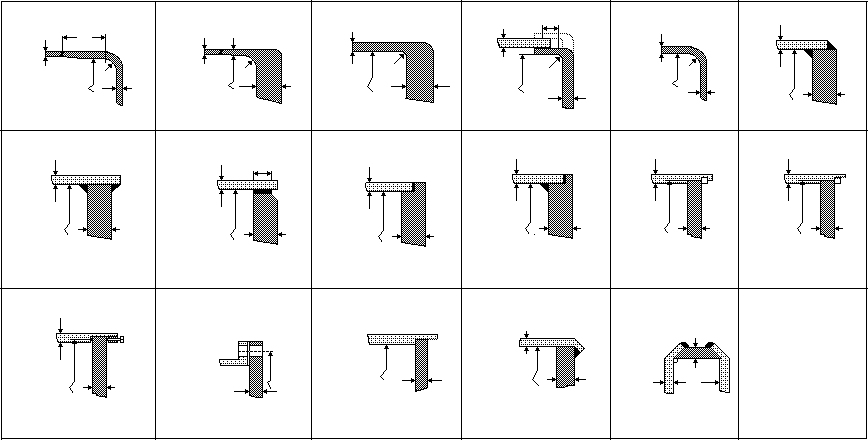
The basic formula t = d·√(C·P/(S·E)) captures the bending of the plate; the structural attachment to the shell enters through the factor C, which ranges between 0.10 and 0.33 depending on the configuration (Figure UG-34). The individual configurations are stored in the module as illustrations, so sketch and factor can be matched unambiguously. For bolted plates with a gasket located outside the bolt circle, the formula is extended by the term with the flange moment from bolt load W and moment arm hG – the moment from the gasket bolting must therefore be considered in addition.
Via UG-39 the module also checks openings in flat heads: openings up to half the head diameter can be verified either through an increased wall thickness (factor 2·C or the 0.75 rule) or through area reinforcement. Anyone who needs to calculate a flat head to ASME thus obtains the complete design check, from configuration selection to opening reinforcement.
Standard and calculation basis: ASME BPVC VIII-1 UG-34 & UG-39: 2025
Calculation workflow
- Select the configuration: From the stored sketches per Figure UG-34, the applicable configuration is selected – forged with transition radius, welded in, flanged, or bolted. This fixes the factor C and the governing design diameter d.
- Define loading and material properties: Design pressure P, allowable stress S at design temperature and joint efficiency E are applied. For some configurations, C additionally depends on the ratio of required to actual shell wall thickness (C = 0.33·m with m = tᵣ/tₛ).
- Calculate the plate thickness: For non-bolted heads, t = d·√(C·P/(S·E)) applies. For bolted plates with the gasket outside the bolt circle, the moment term 1.9·W·h_G/(S·E·d³) is added under the square root; the more unfavourable of the two load cases, operating and gasket seating, governs.
- Verify openings per UG-39: For openings in the head it is checked whether the wall thickness with the doubled factor C (or limited by the factor 0.75 under the square root) is sufficient, or whether area reinforcement around the opening is required. The location and spacing of multiple openings enter into the check.
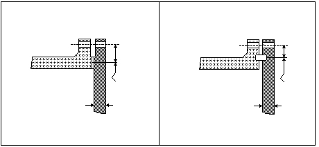
- Set allowances and as-built thickness: Corrosion allowance and manufacturing tolerances are added; for bolted covers the groove depth of gasket grooves must additionally be deducted from the load-bearing thickness.
Input quantities
| Quantity | Symbol | Unit |
|---|---|---|
| Calculation pressure | p0 | MPa |
| Calculation temperature | T0 | °C |
| Design type (Fig. UG-34) Type | Typ | – |
| Outside diameter | D0 | mm |
| Final thickness without allowance | ts | mm |
| Required thickness without allowance | tr | mm |
| Connection length | Y | mm |
| Final thickness for type b1 (≥ 2·ts) | tf | mm |
| Bolting force for installation | WE | N |
| Bolt force for operation | Wm1 | N |
| Lever arm | hg | mm |
| Short span | d | mm |
| Long span | D | mm |
| Perimeter along the bolt holes | L | mm |
| Final wall thickness | th | mm |
| Wall thickness allowance | c1 | mm |
| Allowance (corrosion) | c2 | mm |
| Material | Werkstoff | – |
| Allowable stress operation | SB | MPa |
| Joint efficiency (or Cast Quality Factor) | E | – |
| Design factor | Z | – |
| Design factor | C | – |
| Required thickness | t | mm |
| Minimum required thickness in a groove | tm | mm |
Calculated results
| Quantity | Symbol | Unit |
|---|---|---|
| Bolting force for installation | WE | N |
| Bolt force for operation | Wm1 | N |
| Ratio | m | – |
| Design factor | Z | – |
| Design factor | C | – |
| Required thickness | t | mm |
| Allowable excess pressure | P | MPa(p) |
| Minimum required thickness in a groove | tm | mm |
| Remark | Bemerkung | – |
| Required thickness incl. allowances | t+c1+c2<7sub> | mm |
| Required bend radius | rmin | mm |
| Gasket force for min. pressure | Wm2 | N |
| Allowable pressure without hydrostatic head | MAWP | MPa |
Calculation options
Select Header
Circular flat heads and plates without flange moment · Non-circular flat heads and plates without flange moment · Circular flat heads and plates with flange moment · Non-circular flat heads and plates with flange moment
Worked example
A circular flat head welded into the shell, without openings, is to be sized to ASME BPVC VIII-1, UG-34 – a worked example of how to calculate flat head thickness to the ASME code. For the selected configuration per Figure UG-34 the factor is C = 0.33; the plate is seamless (E = 1.0).
Given values
| Design diameter d | 500 mm |
| Design pressure P | 0.8 MPa (8 bar) |
| Allowable stress S | 138 N/mm² |
| Joint efficiency E | 1.0 |
| Factor C (configuration per Fig. UG-34) | 0.33 |
Solution
Apply the formula per UG-34(c)(2)
For non-bolted flat heads:
t = d · √(C · P / (S · E))
Calculate the required wall thickness
t = 500 · √(0.33 · 0.8 / (138 · 1.0))
t = 500 · √0.001913 = 500 · 0.04374 = 21.87 mm
Set the as-built thickness
With a corrosion allowance of 1 mm the required thickness is 22.87 mm; a plate of, for example, 25 mm thickness is selected.
Result
| Required wall thickness excluding allowances | 21.87 mm |
| Required wall thickness with 1 mm corrosion allowance | 22.87 mm |
All values are illustrative. The applicable standard and project-specific boundary conditions remain authoritative.
Frequently asked questions
What does the factor C depend on and why is it so decisive?
C represents the degree of edge fixity of the plate: a forged head with a generous transition radius acts almost fully clamped (C = 0.17 or 0.10), a simply welded-in plate more like simply supported (C = 0.33). Since C sits under the square root, the difference between 0.17 and 0.33 changes the required thickness by around 40% – picking the wrong sketch from Figure UG-34 is accordingly the most common source of error.
Why do flat heads end up so much thicker than formed heads?
A flat plate carries the pressure in bending, a formed head through membrane tension. Bending makes poor use of the cross-section, so the plate thickness grows with d·√P rather than with P·D/S. From medium diameters and pressures upward, flat heads are therefore economical only as forged components or bolted covers.
What must be considered for a bolted cover in the gasket seating condition?
When the bolts are tightened without internal pressure, only the moment W·h_G from the gasket seating load acts. The code therefore requires checking both load cases – operating (P plus operating bolt load) and gasket seating (bolt load for seating the gasket at ambient temperature). With hard gaskets requiring a high seating load, the seating condition frequently governs.
When is a thicker plate sufficient for an opening in a flat head, and when is reinforcement needed?
UG-39 permits, for single openings up to half the head diameter, the simplified check via an increased plate thickness (using 2·C, limited to 0.75 under the square root). Larger openings, closely spaced openings, or nozzles with high external loads require the area reinforcement check analogous to UG-37, with half the area required there.