Engineering task and calculation objective
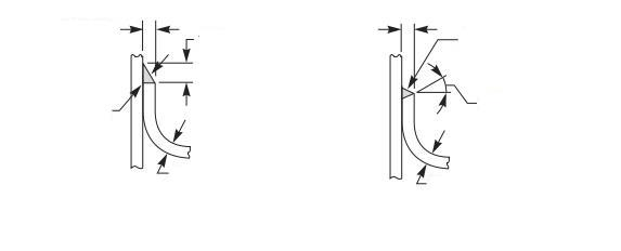
The AP09 module calculates jacketed vessels to ASME BPVC Section VIII, Division 1, Mandatory Appendix 9 — with the focus on the closure member between the inner vessel shell and the jacket. Appendix 9 classifies the jacket types (Type 1 through 5, from the continuous full jacket to the partial jacket resembling a half-pipe coil arrangement) and provides design rules and weld details for the permissible closure constructions — torus closure, conical transition, welded-in closure ring.
Input quantities are the geometry of inner vessel and jacket: outside radius and wall thickness of the inner vessel, inside radius and wall thickness of the jacket, from which the jacket space is derived, and, for the torus closure, the corner radius. The module delivers the required minimum thickness of the closure member and of the jacket wall as well as the required weld dimensions per the detail figures of Appendix 9.
This calculation is needed in pressure vessel fabrication for all heated or cooled vessels with a heating/cooling jacket — agitated vessels, reactors, temperature-controlled storage tanks. The closure of the annular space is almost always the critical item, because there the jacket wall and the vessel wall with different radii and pressures are brought together.
Standard and calculation basis: ASME BPVC VIII-1 Mandatory Appendix 9 2019 Edition
Calculation workflow
- Define jacket type and closure form: First, the design per Appendix 9 is selected: extent of the jacket (full or partial jacket, Type 1–5) and closure form of the annular space (e.g., torus closure, conical closure, welded-on closure ring). The closure form determines the applicable design formulas and permissible weld details from the figures of the Appendix.
- Capture the geometry of the annular space: From the outside radius or diameter of the inner vessel and the inside radius of the jacket, the jacket space j results. Added to this are the nominal wall thicknesses of the inner vessel wall and the jacket wall and, for the torus closure, the corner radius.
- Check the wall thicknesses of the pressure-retaining parts: The jacket wall is verified for the jacket pressure per the rules of UG-27; the inner vessel must additionally be checked for the externally acting jacket pressure (external pressure case per UG-28), unless it is simultaneously under a higher internal pressure.
- Size the closure member: For the selected closure form, Appendix 9 provides the formula for the required minimum thickness of the closure member as a function of jacket pressure, jacket space, and allowable stress. If the jacket wall and the closure are executed with identical thickness, the construction simplifies accordingly.
- Determine the weld dimensions: Finally, the required weld throat dimensions of the attachment welds between closure, jacket, and vessel wall are determined per the permissible details of Appendix 9. The weld dimensions depend on the closure form and the connected wall thicknesses and must be observed in the design.
Input quantities
| Quantity | Symbol | Unit |
|---|---|---|
| Internal design pressure in jacket chamber | P | MPa(p) |
| Design temperature | T | °C |
| Outside radius of inner vessel | Rs | mm |
| Outside diameter of inner vessel | Ds | mm |
| Inside radius of jacket | Rj | mm |
| Choose: Type of Jacket Closure | Closure | – |
| Choose: Type of Jacket Vessel | Vessel | – |
| Nominal thickness of inner vessel wall | tsN | mm |
| Nominal thickness of outer jacket wall | tjN | mm |
| Nominal thickness of closure member | tcN | mm |
| Corner radius of torus closures | r | mm |
| Wall thickness of outer jacket wall and closure member identical | identical | – |
| wall | wall | – |
| K | K | N/mm² |
| SF | SF | - |
| S | S | N/mm² |
| c1 | c1 | mm |
| c2 | c2 | mm |
| Weld dimension | Y | mm |
| closure | closure | – |
| K | K | N/mm² |
| SF | SF | - |
| S | S | N/mm² |
| c1 | c1 | mm |
Calculation options
Choose: Type of Jacket Closure
(a) · (b-1) · (b-2) · (b-3) · (c) · (f-1) · (f-2) · (d-1) · (d-2) · (e-1) · (e-2)
Choose: Type of Jacket Vessel
Type 1 · Type 2 · Type-3 · Type 4 · Type-5
Screw dimension
NonMetricThread · M6 x 1 · M8 x 1.25 · M10 x 1.5 · M12 x 1.75 · M14 x 2 · M16 x 2 · M18 x 2.5 · M20 x 2.5 · M22 x 2.5 · M24x 3 · M27 x 3
Frequently asked questions
Which pressure combinations must be considered for a jacketed vessel?
All realistically possible combinations govern: jacket pressure with the inner vessel unpressurized (external pressure on the inner wall — often the critical case), internal pressure with the jacket unpressurized, and both pressures simultaneously. Special conditions such as vacuum in the inner vessel with full heating steam pressure in the jacket, or the pressure test of one side only, must also be checked. Credit for the counter-pressure is permissible only if it is reliably present in every operating condition.
Why is the jacket space j such an important design quantity?
The closure bridges the annular gap between inner vessel and jacket and is loaded in bending by the jacket pressure over this free width. The required closure thickness grows with the jacket space. A small gap that is still manageable in fabrication keeps closure and welds slender — an unnecessarily large gap drives up the thicknesses and additionally impairs the flow distribution of the heating medium.
What is the corner radius of the torus closure prescribed for?
The torus-shaped closure acts like half a knuckle: the corner radius limits the bending stresses in the transition and enables a low-notch, fully weldable joint. Appendix 9 specifies minimum values for the corner radius as a function of the jacket space; radii that are too small produce high local stresses and are not permitted.
Does Appendix 9 also cover half-pipe jackets?
No — welded-on half-pipe coils are treated in ASME VIII-1 by the separate Appendix EE (nonmandatory) and by literature supplementing the jacketed vessel rules. Appendix 9 applies to conventional jackets with a continuous annular space. Choosing the correct set of rules decides the formulas and permissible weld details.