Engineering task and calculation objective
The AFL module calculates bolted flange connections to ASME BPVC Section VIII, Division 1, Mandatory Appendix 2 — the classical Taylor-Forge method. It covers inserted integral flanges, loose flanges and loose flanges with lapped collar (lap joint), as well as designs with and without a tapered hub. This makes it possible to calculate all custom flanges of a pressure vessel that are not covered by standardized flange tables with pressure-temperature ratings.
The calculation proceeds from the gasket diameter via gasket width and effective gasket width (Table 2-5.2) to the required bolt forces: in the operating condition from the hydrostatic end force plus the residual gasket force via the gasket factor m, in the gasket seating condition from the seating load y (both Table 2-5.1). The flange moments are then formed and the stresses in hub and ring are verified; the rigidity criterion per Appendix 2-14 additionally limits flange rotation. For the gasket seating condition a design for the maximum bolt force is possible.
In practice, the Appendix 2 calculation is needed for main vessel flanges, manway and handhole closures, tubesheet bolted joints, and every custom flange geometry in plant engineering to ASME VIII-1. The module reports all auxiliary variables and delivers the maximum allowable working pressure of the joint.
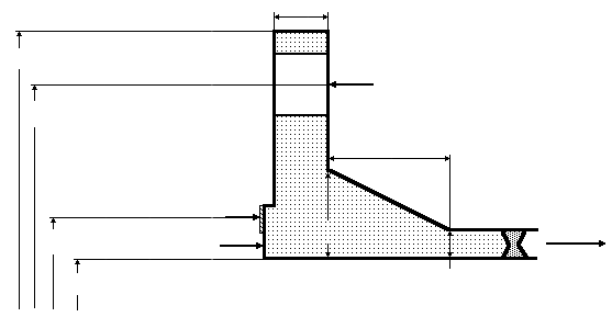
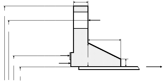
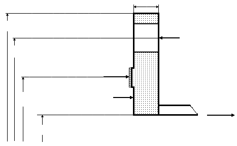
Standard and calculation basis: ASME BPVC VIII Division 1 App. 2: 2023
Calculation workflow
- Select flange type and capture geometry: The flange type (integral flange, loose flange with/without collar, with/without tapered hub) defines the structural model. Flange outside and inside diameter, ring thickness, hub geometry, bolt circle and bolt data as well as design pressure and temperature are captured.
- Determine the gasket quantities: From the gasket diameter and gasket width N, the basic seating width b₀ and from it the effective gasket width b are derived per Table 2-5.2. The gasket factor m and the seating load y from Table 2-5.1 characterize the gasket behavior; the load reaction diameter G locates the line of action of the gasket reaction.
- Bolt forces and bolt area: For the operating condition, W_m1 = H + H_P (hydrostatic end force plus residual gasket force) is calculated; for the gasket seating condition, W_m2 = π·b·G·y. The required bolt cross-sectional area A_m is the maximum from both conditions; it is compared with the actual area A_b of the selected bolts.
- Form the flange moments: The component forces H_D, H_T, and H_G act via their lever arms to the bolt circle. In the gasket seating condition, the moment is formed from the average bolt force 0.5·(A_m+A_b)·S_a — or, on request, from the maximum bolt force if assembly is not force-controlled.
- Stress and rigidity verification: Via the code's shape factors, the longitudinal hub stress S_H, the radial stress S_R, and the tangential stress S_T are calculated and compared with the allowable values for both conditions. The rigidity criterion J ≤ 1 per Appendix 2-14 limits the rotation; finally, the maximum allowable working pressure is reported.
Input quantities
| Quantity | Symbol | Unit |
|---|---|---|
| For -29°C ≤ and | T0 | °C |
| For -29°C ≤ and | P0 | bar |
| Outside diameter Inside diameter | A B | mm |
| Outside diameter Inside diameter | A B | mm |
| Bolt circle diameter Pipe size | C Bn | mm |
| Flange thickness | t | mm |
| Hub length Flange thickness | h t | mm |
| Large hub thickness Small hub thick. | g1 g0 | mm |
| or | /[ ]/( )²/ / | mm |
| Gasket diameter | G | mm |
| Effective gasket width [Table: 2-5.2] | b | mm |
| Gasket factor [Table: 2-5.1] | m | – |
| Gasket seating load [Table: 2-5.1] | y | N/mm² |
| Number | n | – |
| Root diameter | dK | mm |
| Allowable operating stress | Sb | N/mm² |
| Allowable installation stress | Sa | N/mm² |
| Required operation bolt load Eq.(1) | Wm1 | N |
| Minimum initial bolt load Eq.(2) | Wm2 | N |
| Available cross section of bolts | Ab | mm² |
| Required cross section | Wm1/Sb Am1 | mm² |
| Required cross section | Wm2/Sa Am2 | mm² |
| Req. bolt load for gasket seating Eq.(5) | (Am+Ab)·Sa/2 W | N |
| Allowable bolt load | Ab·Sa Wall | N |
Calculation options
Type
Integral Type Flange · Loose Type Flange With Full Neck · Loose Type Flange With Lap · Loose Type Flange without Neck
Worked example
For a vessel flange per ASME VIII-1, Appendix 2, the required bolt forces and the minimum bolt cross-sectional area are to be determined — a worked example of a bolted flange calculation. A spiral-wound gasket (stainless steel with graphite filler) with load reaction diameter G = 320 mm and effective gasket width b = 10 mm is used. Design pressure 16 bar, bolts SA-193 B7.
Given values
| Load reaction diameter of the gasket G | 320 mm |
| Effective gasket width b | 10 mm |
| Design pressure P | 16 bar = 1.6 N/mm² |
| Gasket factor m (spiral-wound, Table 2-5.1) | 3.0 |
| Gasket seating load y (Table 2-5.1) | 69 N/mm² |
| Allowable bolt stress S_a = S_b (SA-193 B7) | 172 N/mm² |
Solution
Hydrostatic end force H
H = π/4 · G² · P = π/4 · (320 mm)² · 1.6 N/mm² = 128,680 N
Residual gasket force H<sub>P</sub> in the operating condition
HP = 2·b · π · G · m · P = 2·10 mm · π · 320 mm · 3.0 · 1.6 N/mm² = 96,510 N
Bolt force, operating condition W<sub>m1</sub>
Wm1 = H + HP = 128,680 N + 96,510 N = 225,189 N ≈ 225.2 kN
Bolt force, gasket seating condition W<sub>m2</sub>
Wm2 = π · b · G · y = π · 10 mm · 320 mm · 69 N/mm² = 693,664 N ≈ 693.7 kN
The gasket seating condition governs here — typical for spiral-wound gaskets with a high seating load.
Required bolt area A<sub>m</sub>
Am = max(Wm1/Sb; Wm2/Sa) = max(225,189/172; 693,664/172) mm² = max(1,309; 4,033) mm² = 4,033 mm²
Selected: 12 bolts M24 (stress area 353 mm² each): Ab = 12 · 353 mm² = 4,236 mm² > Am = 4,033 mm² — sufficient.
Result
| Bolt force, operating condition W_m1 | ≈ 225.2 kN |
| Bolt force, gasket seating condition W_m2 (governing) | ≈ 693.7 kN |
| Required bolt area A_m | 4,033 mm² |
| Selected bolting | 12 × M24 (A_b = 4,236 mm²) |
All values are illustrative. The applicable standard and project-specific boundary conditions remain authoritative.
Frequently asked questions
What do the gasket factor m and the seating load y mean physically?
y is the surface pressure the gasket needs at assembly, as a minimum, to conform to the flange faces and close leakage paths. m describes what multiple of the internal pressure must remain on the gasket as residual pressure in operation for it to stay tight. Both values are empirical values from Table 2-5.1 — not a guarantee of a specific leakage rate; that would require tightness-class-based methods such as EN 1591-1.
When is a loose flange with collar preferable to an integral flange?
The lap-joint flange separates the pressure-retaining part (collar, in contact with the medium) from the bolt load transfer (loose ring). This pays off with expensive corrosion-resistant materials — only the collar needs to be made of the special material, the ring of carbon steel — and when flanges must remain rotatable for alignment. Disadvantages are lower rigidity and usually thicker components for the same pressure.
Why can a joint be strong enough by calculation and still leak?
Appendix 2 is a strength verification for flange and bolts, not a leak-tightness verification. Excessive flange rotation, gasket creep-relaxation, temperature cycling, or uneven tightening can cause leakage even though all stress checks are satisfied. That is why the rigidity criterion per 2-14 was added, and why the assembly procedure and controlled bolt tightening are just as important as the calculation.
What role does the temperature range from -29 °C play in the verifications?
Below -29 °C (-20 °F), ASME VIII-1 imposes additional toughness requirements (impact testing or exemptions per UCS-66) for flange, bolt, and nut materials. The flange calculation itself does not change, but the material selection and the allowable stresses must be qualified for the lowest operating temperature.