Engineering task and calculation objective
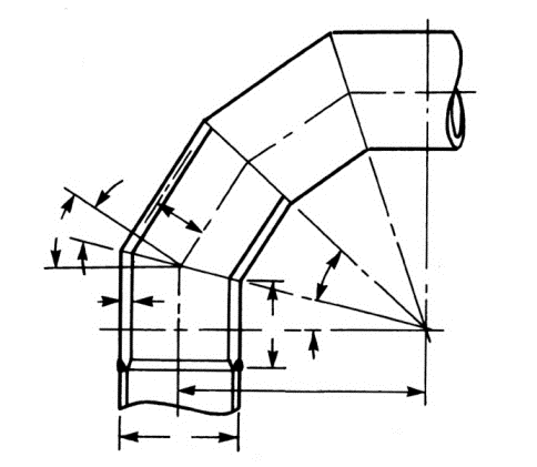
Where standard pipe bends are unavailable or uneconomical — at large nominal sizes, special radii or thick-walled lines — changes of direction are welded as miter bends from obliquely cut pipe segments. This module calculates bends and miter bends with one or more segments under internal pressure per ASME B31.3 (Process Piping) and determines the required wall thickness or the allowable pressure.
At the miter joints of a segmented bend, the kink in the pipe axis produces local stress intensifications that grow with the angle of deflection per joint. ASME B31.3 captures this in Paragraph 304.2.3 with closed-form equations that limit the allowable pressure as a function of miter angle, mean bend radius and wall thickness — with different relations applying to multi-segment bends and to single miters with a large angle. The database of American materials is integrated into the module, so the allowable stresses at design temperature are directly available.
You typically need to calculate a miter bend to ASME B31.3 in plant engineering for large-size process and utility lines, for ducts made of spiral- or longitudinally welded pipe, and when re-rating existing miter bends for changed pressure ratings.
Standard and calculation basis: ASME B31.3: 2022
Calculation workflow
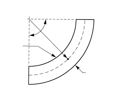
- Define the geometry of the miter bend: Inputs are pipe outside diameter and wall thickness, the number of segments, the angle of deflection per miter joint θ and the mean radius of curvature R1 of the bend run. B31.3 distinguishes bends with θ ≤ 22.5° per joint from single miters with a larger angle.
- Determine material and allowable stress: The allowable stress S at design temperature is taken from the integrated database of ASME materials; together with the quality factor E and the weld joint strength reduction factor W, this yields the allowable stress value of the miter joint welds.
- Calculate the allowable pressure per criterion: Per Para. 304.2.3, the maximum allowable pressure is determined from several equations: one relation that captures the stress intensification at the miter joint via the term with tan θ, and one relation via the radius of curvature. The smallest value governs; for single miters above 22.5°, a separate, more restrictive equation applies.
- Iterate the required wall thickness: Conversely, the module determines the required wall thickness with which all pressure criteria are satisfied — including allowances for corrosion and manufacturing tolerance. Since the wall thickness appears nonlinearly in the equations, this is done iteratively.
- Check the geometric minimum requirements: In addition, the module checks the constructive constraints of the code, such as the minimum distance between the miter welds (minimum land width M at the inside radius) and the minimum required radius of curvature as a function of the nominal size.
Input quantities
| Quantity | Symbol | Unit |
|---|---|---|
| Required wall thickness | s | mm |
| Outside diameter pipe | D | mm |
| Design pressure | p | bar |
| Design pressure | p | N/m² |
| Nominal design strength (operation) | K | N/mm² |
| Wall thickness allowance | c1 | mm |
| Corrosion / wear allowance | c2 | mm |
| Nominal design strength (test) | K' | N/mm² |
| Material | Werkstoff | – |
| Design temperature | T | °C |
| Radius of bend | R1 | mm |
| Distance pipe center - pipe wall | R2 | mm |
| Angle | θ | ° |
| Safety factor (operation) | S | – |
| Safety factor (test) | S' | – |
| Number of segments | Segmente | – |
| Intrados (Inside bend radius) | Ii | – |
| Extrados (Outside bend radius) | Ie | – |
| Required wall thickness without allowance | ti | mm |
| Required wall thickness without allowance | te | mm |
| Coefficient | Y | - |
| Quality factor | E | - |
| Weld joint strength reduction factor | W | - |
| Required wall thickness with allowance | ti | mm |
Calculation options
Number of segments
1 · Multiple
Frequently asked questions
Why is a miter bend weaker than a smooth pipe bend?
At the miter joint the pipe axis kinks; the circumferential membrane stress cannot flow around uniformly there but intensifies locally at the inside of the kink. This intensification grows with the angle of deflection per joint and with the diameter-to-wall-thickness ratio. B31.3 therefore limits the allowable pressure through dedicated equations; many small segments with a small θ approach the behavior of the smooth bend.
Up to what angle does a miter joint count as a bend at all?
B31.3 treats miters with an angle of deflection of up to 3° like straight pipe joints — no special calculation is needed for those. Above that, the miter bend rules of Para. 304.2.3 apply, with the distinction between multi-segment bends (θ ≤ 22.5° per joint) and single miters with a larger angle, for which a considerably more conservative equation applies.
What role does the weld joint strength reduction factor play at the miter joints?
The miter joints are circumferential butt welds oriented transverse to the direction of highest stress. In addition to the quality factor E of the pipe's longitudinal seam, the weld joint strength reduction factor W therefore enters at elevated temperatures. Moreover, many specifications require increased non-destructive examination of the miter welds, since they are both strength- and fatigue-critical.
Are miter bends suitable for cyclically loaded lines?
Only to a limited extent. The notch effect of the miter joints leads to higher stress intensification and flexibility factors than for the smooth bend (Appendix D of B31.3). Under strongly cyclic pressure or temperature loading and under vibration, induction bends or standard bends are preferable; where miter bends are unavoidable, the fatigue evaluation must be carried out with the corresponding factors.