Engineering task and calculation objective
The UG32 module calculates the required wall thickness of formed heads under internal pressure to ASME BPVC Section VIII Division 1, paragraph UG-32 in conjunction with Appendix 1. Covered are ellipsoidal heads (in particular the 2:1 semi-ellipsoidal head), torispherical heads – for Kloepper (DIN dished) and Korbbogen type heads the program presets the geometry ratios automatically –, hemispherical heads, and conical shells with and without a knuckle, including the cone-to-cylinder junctions at the large and small end.
In practice this calculation is needed for every pressure vessel designed to the ASME code: the head closes the cylindrical shell, and its wall thickness depends on head shape, design pressure, the allowable stress of the material at design temperature and the joint efficiency E. Appendix 1 provides supplementary formulas, for instance for ellipsoidal heads of arbitrary aspect ratio (factor K) and torispherical heads with an arbitrary ratio of crown radius to knuckle radius (factor M).
The module reports the required wall thickness with and without allowances, additionally checks the spherical crown region within 0.8·D per paragraph (c) using the equivalent spherical diameter, and, conversely, calculates the maximum allowable pressure for a given wall thickness – with and without the hydrostatic head.
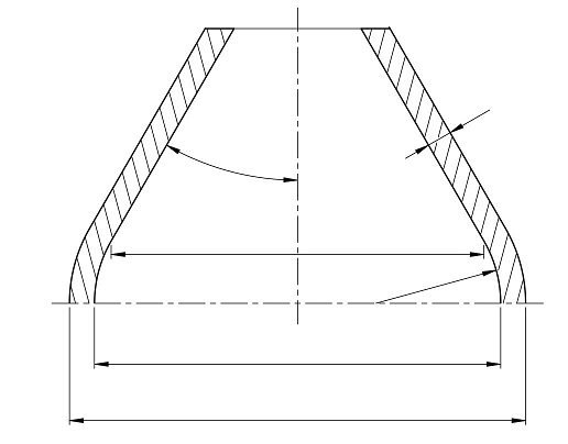
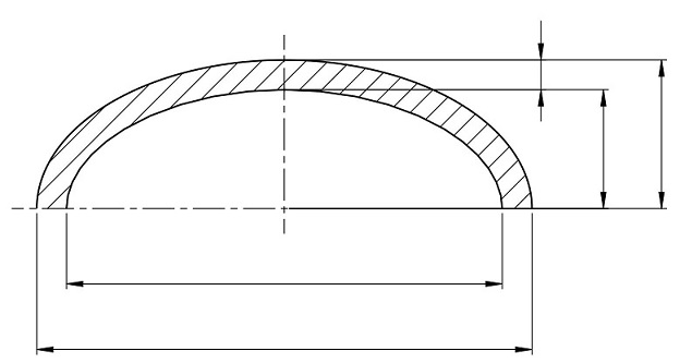
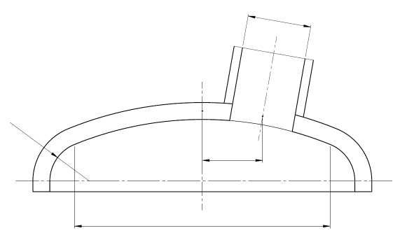
Standard and calculation basis: ASME BPVC VIII-1 UG-32 & Appendix-1: 2025
Calculation scope
- Elliptical heads under internal pressure
- Torispherical heads (Kloepper, Korbbogen, Semi-spherical) under internal pressure
- Cone without knuckle under internal pressure
- Cone with knuckle under internal pressure
- Cone-to-cylinder junction at large end under internal pressure
- Cone-to-cylinder junction at small end under internal pressure
Calculation workflow
- Define head shape and geometry: First the head shape is selected: ellipsoidal, torispherical (Kloepper or Korbbogen type with program-preset geometry), hemispherical or conical. This fixes the diameter, crown radius L, knuckle radius r, or the half-apex angle of the cone.
- Determine the shape factors: The factors are calculated from the geometry ratios: K for ellipsoidal heads from the aspect ratio (K = 1 for the 2:1 head), M for torispherical heads from the ratio L/r, and factor K1 per Table UG-37 for the equivalent spherical diameter.
- Apply material properties and joint efficiency: The allowable stress S of the head material at design temperature is taken from ASME Section II Part D; the joint efficiency E depends on weld type and extent of examination. For comparison the module also reports the result per UG-32 with E = 1.
- Calculate the required wall thickness: The required wall thickness is determined with the governing formula – e.g. t = P·D/(2·S·E − 0.2·P) for the 2:1 ellipsoidal head or t = P·L·M/(2·S·E − 0.2·P) for torispherical heads. For the crown region within 0.8·D, the supplementary check per paragraph (c) is performed using the equivalent spherical outside diameter.
- Add allowances and report the allowable pressure: Corrosion and wall thickness allowances are added to obtain the required as-built wall thickness. Conversely, for a chosen wall thickness the module calculates the maximum allowable pressure with and without the hydrostatic head of the vessel contents.
Input quantities
| Quantity | Symbol | Unit |
|---|---|---|
| Calculation pressure | p0 | MPa(p) |
| Calculation temperature | T0 | °C |
| Effective thickness without allowances | t0 | mm |
| Inside diameter of cylindrical shell | D | mm |
| Outside diameter of cylindrical shell | D0 | mm |
| Equivalent radius | L | mm |
| Half-apex angle (≤30°) | α | ° |
| Knuckle radius | r | mm |
| Largest inside diameter of cone | Di | mm |
| Material | Boden | – |
| Allowable stress | S | MPa |
| Weld joint efficiency (or Cast Quality Factor) | E | – |
| Required thickness | t | mm |
| Allowable excess pressure incl. hydrost. head | P | MPa(p) |
| Inside depth of head (minor semi-axis= h0-t0) | h | mm |
| Final wall thickness | te | mm |
| Wall thickness allowance | c1 | mm |
| Allowance (corrosion) | c2 | mm |
| Ratio | L/r | – |
| Factor | M | – |
| Axial load based on circumference (for compression negative) | f1 | N/mm |
| Axial load based on circumference (for compression negative) | f2 | N/mm |
| with allowances | t1 | mm |
| Wall thickness allowance | c1 | mm |
Calculated results
| Quantity | Symbol | Unit |
|---|---|---|
| Half-apex angle (≤30°) | α | ° |
| Required thickness | t | mm |
| Allowable excess pressure incl. hydrost. head | P | MPa(p) |
| Final wall thickness | te | mm |
| Ratio | D/2h | – |
| Factor | K | – |
| with allowances | t1 | mm |
| with allowances | t2 | mm |
| Factor | k | – |
| Ratio | P0/SsE1 | – |
| Angle | Δ | ° |
| Effective load | QL | N/mm |
| Effective load | QS | N/mm |
| Required cross sectional area | ArL | mm² |
| Required cross sectional area | ArS | mm² |
| Required thickness cylinder (UG-27) | t | mm |
| Required thickness cone (UG-32) | tr | mm |
| incl. allowances | (te ≥t+) t+ | mm |
| Available cross section | AeL | mm² |
| Available cross section | AeS | mm² |
| Required area of reinforcement | Ar | mm² |
| Factor K1 acc. Table UG-37 | K1 | – |
| Bedingungen | Bedingungen | – |
| Festigkeit | Festigkeit | – |
Worked example
For a vertical pressure vessel, determine the required wall thickness of a 2:1 semi-ellipsoidal head under internal pressure to ASME BPVC VIII-1, UG-32 – a typical worked example for anyone who needs to calculate head thickness to the ASME code. The allowable stress of the material at design temperature is 138 N/mm²; the head is seamless (E = 1.0).
Given values
| Inside diameter D | 1,600 mm |
| Design pressure P | 1.0 MPa (10 bar) |
| Allowable stress S | 138 N/mm² |
| Joint efficiency E | 1.0 |
| Corrosion allowance c | 1.0 mm |
| Head type | 2:1 semi-ellipsoidal head (K = 1) |
Solution
Apply the formula per UG-32(d)
For the 2:1 semi-ellipsoidal head:
t = P · D / (2 · S · E − 0.2 · P)
Calculate the required wall thickness
t = 1.0 · 1,600 / (2 · 138 · 1.0 − 0.2 · 1.0)
t = 1,600 / 275.8 = 5.80 mm
Add allowances
treq = 5.80 + 1.0 = 6.80 mm
The next available plate thickness is selected, e.g. 8 mm; this also covers manufacturing tolerances and the thinning during forming, which the manufacturer has to verify.
Result
| Required wall thickness excluding allowances | 5.80 mm |
| Required wall thickness including corrosion allowance | 6.80 mm |
All values are illustrative. The applicable standard and project-specific boundary conditions remain authoritative.
Frequently asked questions
Can I calculate Kloepper and Korbbogen heads directly to ASME?
Yes, via Appendix 1-4. The Kloepper head (L = D, r = 0.1·D) and the Korbbogen head (L = 0.8·D, r = 0.154·D) are torispherical heads whose factor M is determined from the ratio L/r. The short-form equation given in UG-32, by contrast, applies only to the standard torispherical head with L = D and r = 0.06·L – it must not be carried over to Kloepper geometry without checking.
How does the ASME approach differ from the Kloepper head calculation per the German AD 2000 code, Merkblatt B 3?
ASME sizes formed heads via the membrane formula with a shape factor (K or M) and covers the knuckle stresses implicitly through it. AD 2000 B 3, in contrast, uses a separate design coefficient β for the knuckle and additionally checks elastic buckling of the knuckle under internal pressure. The results can differ, particularly for thin-walled large heads; the code agreed for the vessel governs.
What is the purpose of the paragraph (c) check in the crown region?
Torispherical and ellipsoidal heads may alternatively be verified in the central crown region (within 0.8·D) as a spherical shell with the equivalent spherical radius. This is relevant when the head is fabricated from crown and knuckle with different wall thicknesses, or when openings in the crown have to be reinforced per UG-37 – there the equivalent spherical diameter enters the opening reinforcement calculation.
What role does the hydrostatic head play in the allowable pressure?
In vertical vessels containing liquid, the hydrostatic pressure of the liquid column acts at the lowest point in addition to the operating overpressure. The module therefore reports the allowable pressure once including and once excluding the hydrostatic head – making it immediately visible how much of the pressure budget is consumed by the vessel contents.