Engineering task and calculation objective
The UG33 module calculates formed heads under external pressure to ASME BPVC Section VIII Division 1, paragraph UG-33 in conjunction with Appendix 1. Covered are ellipsoidal, torispherical (Kloepper and Korbbogen type heads with program-preset geometry), hemispherical and conical heads. The check is needed wherever heads are loaded from the outside: on vacuum vessels, in the jacket spaces of heated equipment, or on internal heads with pressure acting on the convex side.
Under external pressure it is not strength but buckling stability that governs. The heads are treated as a spherical shell with the design radius of the crown: from the ratio of radius to wall thickness the strain factor A is determined, and the stress factor B is read from the material-temperature charts of ASME Section II Part D. In addition, the code requires the wall thickness to satisfy the internal pressure calculation to UG-32 with 1.67 times the external pressure (and E = 1).
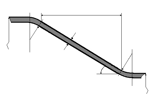
For conical heads the module additionally sizes the corner junctions at the large and small end: the cross-section and effective moment of inertia of the stiffening at the cone-to-cylinder junction are verified. The results are the allowable external pressure with and without the hydrostatic head and the required wall thickness with and without allowances.
Standard and calculation basis: ASME BPVC VIII-1 UG-33 & Appendix-1: 2025
Calculation workflow
- Define head shape and design radius: Depending on the head shape, the governing design radius of the crown is determined: the spherical radius for the hemispherical head, the crown radius L for the torispherical head, or the equivalent spherical radius K1·Dₒ for the ellipsoidal head per chart UG-33.1.
- Form the ratio and determine factor A: From the ratio of outside crown radius to wall thickness, the strain factor A = 0.125/(Rₒ/t) is formed – the critical buckling strain of the equivalent spherical shell.
- Read factor B from the material chart: Using factor A, the stress factor B is determined from the material-temperature chart of the head material; to the left of the start of the curve the elastic relationship via the modulus of elasticity applies. The allowable external pressure follows from Pₐ = B/(Rₒ/t).
- Perform the parallel check per UG-32: In addition, the wall thickness must withstand the internal pressure formula per UG-32, applied with 1.67 times the external pressure and joint efficiency E = 1. The larger of the two wall thickness values governs.
- Cones: verify the corner junctions: For conical heads under external pressure the module checks the transitions at the large and small end: the required stiffening cross-sections and effective moments of inertia of the corner junction are determined per Appendix 1 and compared with the actual values.
- Report results including allowances: The required wall thickness is determined iteratively and reported once without and once with corrosion and manufacturing allowances; the allowable external pressure appears with and without the hydrostatic head.
Input quantities
| Quantity | Symbol | Unit |
|---|---|---|
| Calculation pressure | p0 | bar |
| Calculation temperature | T0 | °C |
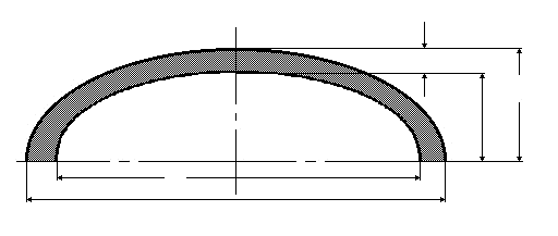
| Effective thickness | t0 | mm |
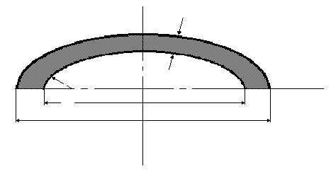
| Outside diameter of the head skirt | D0 | mm |
| Outer height of crown (short semiaxis) | h0 | mm |
| Outside calotte radius | R0 | mm |
| Outside diameter ( wide end ) | DLs | mm |
| Knuckle radius ( wide end ) | r1 | mm |
| Outside diameter ( small end ) | DSs | mm |
| Knuckle radius ( small end ) | r2 | mm |
| Half apex angle (≤ 60°) | α | ° |
| Ratio | R0/t0 | – |
| Knuckle radius | r | mm |
| Material | Werkstoff | – |
| Allowable stress | S0 | N/mm² |
| Applicable material chart | Fig | – |
| Modulus of elasticity | E | N/mm² |
| Factor | A | – |
| Factor (see material chart) | B | N/mm² |
| Allowable external pressure | P | MPa(p) |
| Required thickness | t | mm |
| Spec. Min. Yield | Sy | N/mm² |
| Design wall thickness | te | mm |
| Wall thickness allowance | c1 | mm |
Calculated results
| Quantity | Symbol | Unit |
|---|---|---|
| Ratio | D0/2h0 | – |
| Factor (according to chart UG-33.1) | K0 | – |
| Outside calotte radius | R0 | mm |
| Axial length of the cone | L | mm |
| Design length | Le | mm |
| Ratio | Le/DL | – |
| Ratio | DL/te | – |
| Ratio | R0/t0 | – |
| Factor | A | – |
| Factor (see material chart) | B | N/mm² |
| Factor | 2·Min(S0;.9·B) S | N/mm² |
| Allowable external pressure | P | MPa(p) |
| Required thickness | t | mm |
| Equivalent length | M | mm |
| Effective load | FL | N/mm |
| Effective load | FS | N/mm |
| Reference area | ATL | mm² |
| Reference area | ATS | mm² |
| Required moment of inertia | Is | mm^4 |
| Required moment of inertia | I's | mm^4 |
| Length of support | 0.55·√(D·ts) | mm |
| Available moment of inertia | I' | mm^4 |
| Equivalent length | N | mm |
| Remark | Bemerkung | – |
Frequently asked questions
Why must a head under external pressure additionally be calculated per UG-32 with 1.67 times the pressure?
The buckling check via factors A and B covers stability failure, but not the bending and membrane stresses in the knuckle. The code therefore requires, in parallel, the strength check using the internal pressure formulas with 1.67 times the external pressure and E = 1. For thick-walled small heads this check frequently governs; for thin-walled large heads the buckling check does.
Which radius applies to ellipsoidal heads under external pressure?
The ellipsoidal head is represented by an equivalent spherical radius K1·Dₒ, where K1 per chart UG-33.1 depends on the aspect ratio (for the 2:1 head K1 = 0.9). A common error is to use the crown radius from the internal pressure calculation or half the diameter here – both lead to incorrect buckling results.
When do cones under external pressure need stiffening at the corner junction?
At the cone-to-cylinder transition circumferential compressive forces arise that load the junction like a stiffening ring. The code requires a sufficient effective cross-section and moment of inertia there; shell and cone portions within the effective width may be counted. If the available cross-section is insufficient, a ring must be provided at the junction.
Should a Kloepper head under external pressure be expected to have the same wall thickness as under internal pressure?
No. Under external pressure the crown, with its large radius, is prone to buckling, so torispherical heads often need considerably thicker walls here than the internal pressure check alone would suggest. For vacuum vessels it is therefore worth comparing with a Korbbogen or ellipsoidal head, whose smaller crown radius relieves the buckling check.