Engineering task and calculation objective
The AP14 module calculates welded (integral) flat heads with a large, single, circular, centrally located opening to ASME BPVC Section VIII, Division 1, Mandatory Appendix 14. Such heads fall outside the scope of the normal opening reinforcement rules of UG-39: as soon as the opening diameter exceeds half the head diameter, the head no longer acts as a full plate but as an annular plate — and precisely for this case Appendix 14 provides the verification procedure.
The method treats the configuration of shell, flat annular head, and central nozzle or connecting pipe as one coherent system: at both junctions (shell-to-head and head-to-nozzle), edge moments and forces are determined from the compatibility of deformations; from these, longitudinal and circumferential stresses in shell, head, and nozzle are calculated and compared with the allowable values — partly with increased limits reflecting their secondary stress character. The module can display the equations used, for traceability.
Typical applications in pressure vessel design are flat heads with a central manway or dome nozzle, filter housing covers with a large connection, and shell-and-tube equipment with a central penetration — everywhere the simple flat head formula of UG-34 in conjunction with UG-39 is no longer applicable.
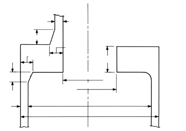
Standard and calculation basis: ASME VIII-1 Mandatory Appendix 14
Calculation workflow
- Check applicability: First it is checked whether the opening is single, circular, and central, and whether its diameter exceeds the limit for normal area reinforcement per UG-39 (d greater than half the head diameter). Only then is Appendix 14 to be applied; smaller openings are reinforced conventionally.
- Capture geometry and stiffnesses: Shell diameter and thickness, head thickness, opening diameter, and the wall thickness and length of the attached nozzle are captured. From these quantities, the stiffness parameters of the three components for the compatibility analysis are formed.
- Determine edge moments from deformation compatibility: At the shell-to-head and head-to-nozzle junctions, the rotation and radial displacement of the components must coincide. From these compatibility conditions follow the edge moments and shear forces under design pressure — the core of the Appendix 14 procedure.
- Calculate the stresses: With the edge loads, the longitudinal and circumferential stresses at the governing locations (head ring inner and outer edge, shell and nozzle junction, each on the inside and outside surface) are evaluated as the sum of membrane and bending components.
- Perform the verifications: The stresses are compared with the allowable values, with Appendix 14 permitting increased limits for the bending-dominated components of secondary stress character. If a check fails, the head thickness, nozzle thickness, or the junction design must be adjusted and the calculation repeated.
Input quantities
| Quantity | Symbol | Unit |
|---|---|---|
| Outside diameter of flat head and shell | A | mm |
| Inside diameter | B | mm |
| Outside diameter | B1 | mm |
| Thickness of hub at small end | g0 | mm |
| Thickness of hub at back of flange | g1 | mm |
| Thickness of hub at small end | g0 | mm |
| Thickness of hub at back of flange | g1 | mm |
| Outside diameter | B1 | mm |
| Inside diameter | Bs | mm |
| Length of nozzle transition | hn | mm |
| Internal design pressure | P | MPa(p) |
| Flat head nominal thickness | t | mm |
| Length of shell transition | hs | mm |
| Type of flange | flange? | – |
| Ratio of outside diameter of flange to inside diameter of flange | K | - |
| Diameter of location of gasket load reaction | G | mm |
| Bolt-circle diameter | C | mm |
| Flange design bolt load | W | N |
| Bolt space | BSp | mm |
| Bolt space correction | BSc | - |
| Nominal bolt diameter | a | mm |
| Temperature | ϑ | °C |
| Material | head | – |
| Nominal design strength | k | MPa(p) |
Calculated results
| Quantity | Symbol | Unit |
|---|---|---|
| Factor for integral type flanges (from figure 2-7.2) - nozzle | FNoz | - |
| Factor for integral type flanges (from figure 2-7.3) - nozzle | VNoz | - |
| Hub stress correction factor for integral type flanges (from figure 2-7.6) - nozzle | fNoz | - |
| Factor nozzle | h0,Noz | - |
| Factor shell | h0,shell | - |
| Hub stress correction factor for integral type flanges (from figure 2-7.6) - shell | fshell | - |
| Factor for integral type flanges (from figure 2-7.3) - shell | Vshell | - |
| Factor for integral type flanges (from figure 2-7.2) - shell | Fshell | - |
| Factor | X1 X1 | - |
| Total moment acting upon the flange | M0 | N·mm |
| Slope of head with central opening or nozzle | (Eθ)* | MPa(p) |
| Moment acting at shell-to-flat head juncture | MH | N·mm |
| Calculated longitudinal stress in hub | SH | MPa(p) |
| Calculated radial stress in flange | SR | MPa(p) |
| Calculated tangential stress in flange | ST | MPa(p) |
| Ratio h/h0 - nozzle | hn/h0n | - |
| Ratio g1/g0 - nozzle | g1n/g0n | - |
| Calculated longitudinal stress in hub | SHS | MPa(p) |
| Calculated radial stress in flange | SRS | MPa(p) |
| Calculated tangential stress in flange | STS | MPa(p) |
| Calculated longitudinal stress in hub opening | SHO | MPa(p) |
| Calculated radial stress in flange opening | SRO | MPa(p) |
| Calculated tangential stress in flange opening | STO | MPa(p) |
| Factor involving K (from figure 2-7.1) | Z Z | - |
Calculation options
Type of flange
Loose flange · Integral flange
Consider boundary moment (gasket)
No · Yes
Frequently asked questions
From what size on does an opening in a flat head count as 'large'?
The limit of the normal reinforcement calculation per UG-39 lies at an opening diameter of half the head diameter. Beyond that, the model of local area reinforcement breaks down because the head globally acts as an annular plate — then Appendix 14 is mandatory. The procedure does not apply to multiple or off-center large openings; there, only U-2(g) with supplementary analysis remains.
Why may some stresses in Appendix 14 exploit higher limits?
The edge moments at the junctions arise from restrained deformation, not directly from pressure equilibrium. Such stresses are partly of secondary character: they relax under local plastic action without the component failing. The code therefore permits increased allowable values for them (up to a multiple of the basic allowable stress), while pure membrane components remain strictly limited.
What role does the welded-on nozzle play for the head thickness?
The central nozzle acts as an elastic restraint of the inner head edge. A thick-walled, sufficiently long nozzle absorbs edge moments and relieves the head noticeably; a thin, short nozzle lets the edge rotate almost freely and increases the head bending. Nozzle thickness and length are therefore genuine design quantities, not merely constructional details.
Does Appendix 14 also apply to bolted or loose-mounted flat covers?
No. The procedure presupposes welded, integral heads in which the head is connected to shell and nozzle with full bending continuity. Bolted covers with a large opening follow different load paths (bolt forces, gasket reaction) and are treated via UG-34 in conjunction with Appendix 2 and special rules.