Engineering task and calculation objective
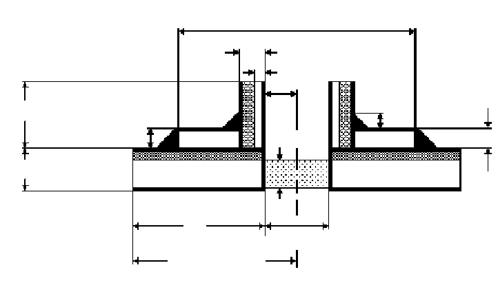
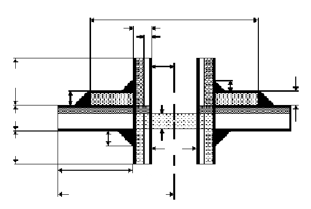
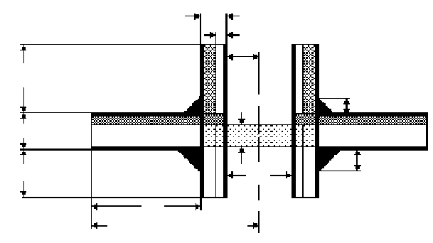
The UG37 module performs the opening reinforcement check for nozzles to ASME BPVC Section VIII Division 1, paragraph UG-37 – the classic area replacement method. It calculates inserted (set-through) and set-on nozzles, each with or without a reinforcing pad, in cylindrical shells, spheres, formed heads and flat heads. Via UG-42, adjacent nozzles can additionally be verified, taking over the values of the single nozzles.
The basic idea: every opening removes load-bearing cross-section from the pressure-loaded wall. The removed area A = d·tr·F must be available again within the limits of reinforcement around the opening – as wall thickness reserve of the shell (A1), reserve of the nozzle wall outside and inside (A2, A3), weld cross-sections (A41–A43) and reinforcing pad (A5). The correction factor F per Fig. UG-37 accounts for the orientation of the examined plane relative to the circumferential direction, and the strength reduction factors fr for the different materials of nozzle, pad and shell.
The module reports required and available areas together with the usage factor, calculates the allowable pressure of the reinforced opening, checks the limits of reinforcement per UG-40, and verifies the required fillet and groove weld thicknesses of the nozzle attachment. Anyone who needs to calculate nozzle reinforcement to ASME thus obtains the complete design check in a single run.
Standard and calculation basis: ASME BPVC VIII-1 UG-37: 2025
Calculation scope
- Protruding nozzles with reinforcement
- Protruding nozzles without reinforcement
- Set-on nozzles with reinforcement
- Set-on nozzles without reinforcement
- Adjacent nozzles (UG-42)
Calculation workflow
- Determine the required wall thicknesses of the undisturbed component: First the required wall thicknesses tᵣ of the shell (per UG-27 or UG-32) and tᵣₙ of the nozzle are determined – each with E = 1, since the area method assumes seamless conditions at the opening.
- Calculate the required reinforcement area: The required area follows from A = d·tᵣ·F, with the opening diameter d in the corroded condition and the correction factor F per Fig. UG-37 (F = 1 in the plane transverse to the vessel axis, down to 0.5 in the longitudinal direction for cylinders).
- Set the limits of reinforcement: The contributing regions are limited: parallel to the wall to the larger of d and Rₙ + t + tₙ on each side, normal to it to 2.5·t or 2.5·tₙ (plus pad thickness) per UG-40. Only material within these limits counts as reinforcement.
- Sum the available areas: Shell reserve A₁, nozzle reserves A₂ and A₃, weld areas A₄ and, if applicable, the reinforcing pad A₅ are added – with the strength reduction factors fᵣ for differing materials – to the available area ∑A and compared with the required area; this yields the usage factor.
- Check welds and load paths: The required fillet and groove weld thicknesses of the nozzle attachment are checked per UG-41/UW-16, including the load path evaluation of which force is transferred through which weld combination.
- Evaluate adjacent nozzles per UG-42: If two openings are closer together than twice their average diameter, the ligament between them is verified: the total available area ∑Aab and the required ligament area are compared; no area may be counted twice.
Input quantities
| Quantity | Symbol | Unit |
|---|---|---|
| Calculation pressure | p0 | MPa(p) |
| Calculation temperature | T0 | °C |
| Factor (1=internal pressure; 2=external pressure) | Γ | – |
| Nominal thickness without allowances | t | mm |
| Required thickness without allowances | tr | mm |
| Material | Mantel | – |
| Allowable stress value | Sv | MPa |
| Joint efficiency factor (or Cast Quality Factor) | E1 | – |
| Correction factor (Fig.UG-37, int. pres.) | F | – |
| Nozzle | Nº | – |
| Nominal thickness with allowances | tn1 | mm |
| Wall thickness allowance | c1 | mm |
| Allowance (corrosion) | c2 | mm |
| Nominal thickness without allowances | tn | mm |
| Outside diameter | da | mm |
| Inside diameter, corroded = da-2·tn | d | mm |
| Internal projection | h | mm |
| Minimum required thickness of nozzle | trn | mm |
| Fillet weld nozzle / shell outside | leg1 | mm |
| Fillet of reinforcement / shell outside | leg2 | mm |
| Material | Stutzen | – |
| Safety factor | S | – |
| Allowable stress | Kn/S Sn | MPa |
| Thickness | te | mm |
Calculated results
| Quantity | Symbol | Unit |
|---|---|---|
| Ligament area > req. total area / 2 | anw | – |
Calculation options
Factor (1=internal pressure; 2=external pressure)
Internal pressure · External pressure
Access opening
No · Yes
Shape of the shell
cylindrical · spherical · Other
Option
Protruding nozzle with reinforcement · Protruding nozzle without reinforcement · Set-on nozzle with reinforcement · Set-on nozzle without reinforcement · Adjacent nozzles acc. to UG-42
Worked example
An inserted nozzle without a reinforcing pad in a cylindrical shell is to be verified to ASME BPVC VIII-1, UG-37 – a worked example of the area replacement method for nozzle reinforcement. Nozzle and shell are of the same material (fᵣ = 1), and the examined plane is transverse to the vessel axis (F = 1). The weld areas are conservatively neglected in this example.
Given values
| Inside radius of shell R | 600 mm |
| Wall thickness of shell t | 14 mm |
| Inside diameter of nozzle d | 200 mm |
| Wall thickness of nozzle tn | 10 mm |
| Design pressure P | 1.6 MPa (16 bar) |
| Allowable stress S | 138 N/mm² |
| Factors | E = 1; F = 1; fr1 = fr2 = 1 |
Solution
Required wall thicknesses per UG-27 (E = 1)
Shell: tr = P·R/(S·E − 0.6·P) = 1.6 · 600 / (138 − 0.96) = 7.01 mm
Nozzle: trn = P·Rn/(S·E − 0.6·P) = 1.6 · 100 / 137.04 = 1.17 mm
Required reinforcement area
A = d · tr · F = 200 · 7.01 · 1 = 1,401 mm²
Available area A1 (shell reserve)
A1 = larger of d·(E1·t − F·tr) = 200 · (14 − 7.01) = 1,399 mm²
and 2·(t + tn)·(E1·t − F·tr) = 2 · 24 · 6.99 = 336 mm²
A1 = 1,399 mm²
Available area A2 (outward nozzle reserve)
A2 = smaller of 5·t·(tn − trn) = 5 · 14 · 8.83 = 618 mm²
and 5·tn·(tn − trn) = 5 · 10 · 8.83 = 442 mm²
A2 = 442 mm²
Verification
∑A = A1 + A2 = 1,399 + 442 = 1,841 mm² ≥ A = 1,401 mm²
Usage factor: 1,401 / 1,841 = 76% — the opening is adequately reinforced without a reinforcing pad; the weld areas actually present increase the margin further.
Result
| Required area A | 1,401 mm² |
| Available area ∑A (excluding welds) | 1,841 mm² |
| Usage factor | approx. 76% |
All values are illustrative. The applicable standard and project-specific boundary conditions remain authoritative.
Frequently asked questions
When may the reinforcement calculation be omitted?
UG-36(c)(3) exempts small openings: in walls up to 10 mm thick, openings up to DN 89 (3½ in.) are permitted without individual verification, in thicker walls up to DN 60 (2⅜ in.), provided minimum spacings between unreinforced openings are observed. Caution: restrictions apply to clusters of such openings and to rapid pressure cycling.
Why is the required wall thickness in the check calculated with E = 1?
The area method compares locally removed and locally available cross-section. The joint efficiency E of the shell's longitudinal seam has nothing to do with this, as long as the opening does not lie in the seam; therefore tᵣ is determined with E = 1. If the nozzle penetrates a welded seam with E < 1, this must be accounted for separately.
What is the effect of the strength reduction factor fᵣ with differing materials?
If the nozzle or the reinforcing pad has a lower allowable stress than the shell, its area only counts proportionally (fᵣ = Sₙ/Sᵥ ≤ 1). A higher-strength nozzle material, however, earns no bonus – fᵣ is capped at 1. A common error is to credit pads made of lower-strength material with their full area.
Is the UG-37 check also sufficient for nozzles with high piping loads?
No. The area replacement method covers only the pressure loading. External forces and moments from the connected piping require an additional check of the local membrane and bending stresses, for instance per WRC 107/537 or WRC 297, or by FEA. Especially for large nozzles in thin-walled vessels, this check often governs.